Infrared UAV Thermal Modules: Engineering Guide for OEM Integration & Edge AI
Infrared UAV Thermal Modules: Engineering Guide for OEM Integration & Edge AI
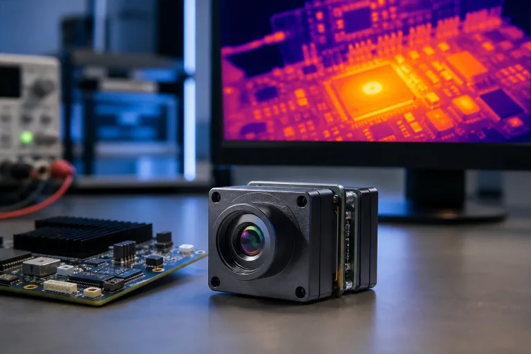
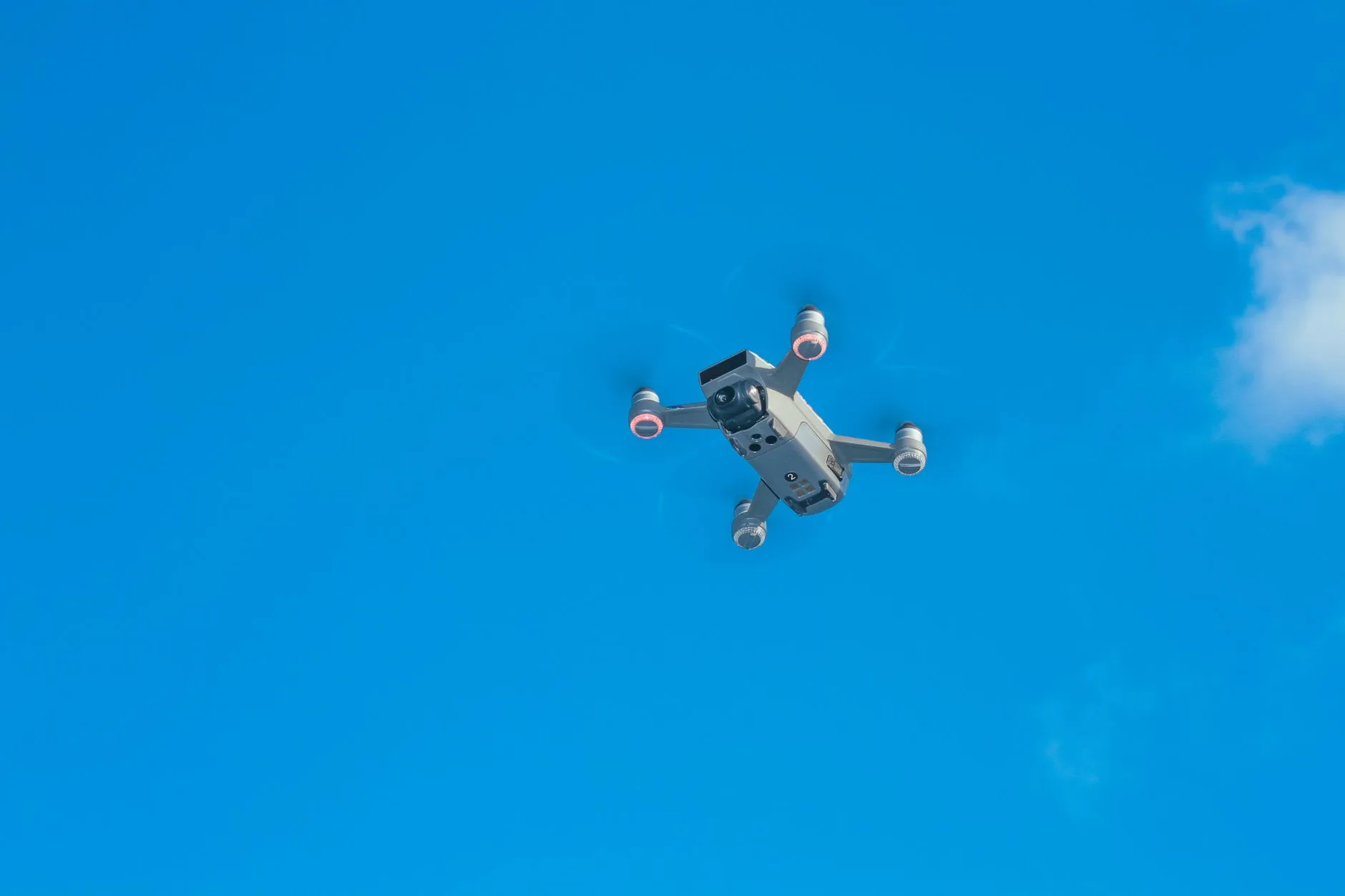
Designing high-reliability aerial vision payloads means balancing tough engineering trade-offs between thermal sensitivity, raw compute throughput, aerodynamic weight budgets, and real-time control latency. Modern autonomous airframes are leaving behind passive imaging sensors that just stream compressed video down to a ground station. In the shop, original equipment manufacturers (OEMs) and unmanned aerial vehicle (UAV) integrators are now mounting unified thermal and electro-optical (EO) edge AI stacks that run neural network inference directly on the airframe silicon.
Whether you’re building a multirotor for industrial perimeter defense, a long-endurance fixed-wing platform for pipeline inspection, or an agile tactical interceptor, integrating an infrared UAV subsystem requires disciplined systems engineering. You cannot simply bolt a thermal core onto an airframe, run standard composite video lines, and hope for stable tracking. Every millivolt of electrical ripple, thermal hotspot on your carrier board, and millisecond of communication lag will degrade mission performance.
Here’s the deal: raw video downlinks are inherently vulnerable to RF jamming, signal dropouts, and unacceptable latency. By moving deep learning inference directly onto the aircraft’s physical compute stack, your platform continues tracking, classifying, and guiding gimbal drives even if the telemetry link drops entirely. This guide breaks down sensor physics, edge AI compute hardware, flight controller protocols, thermal management strategies, and bench-to-flight validation workflows for mission-critical airframes.
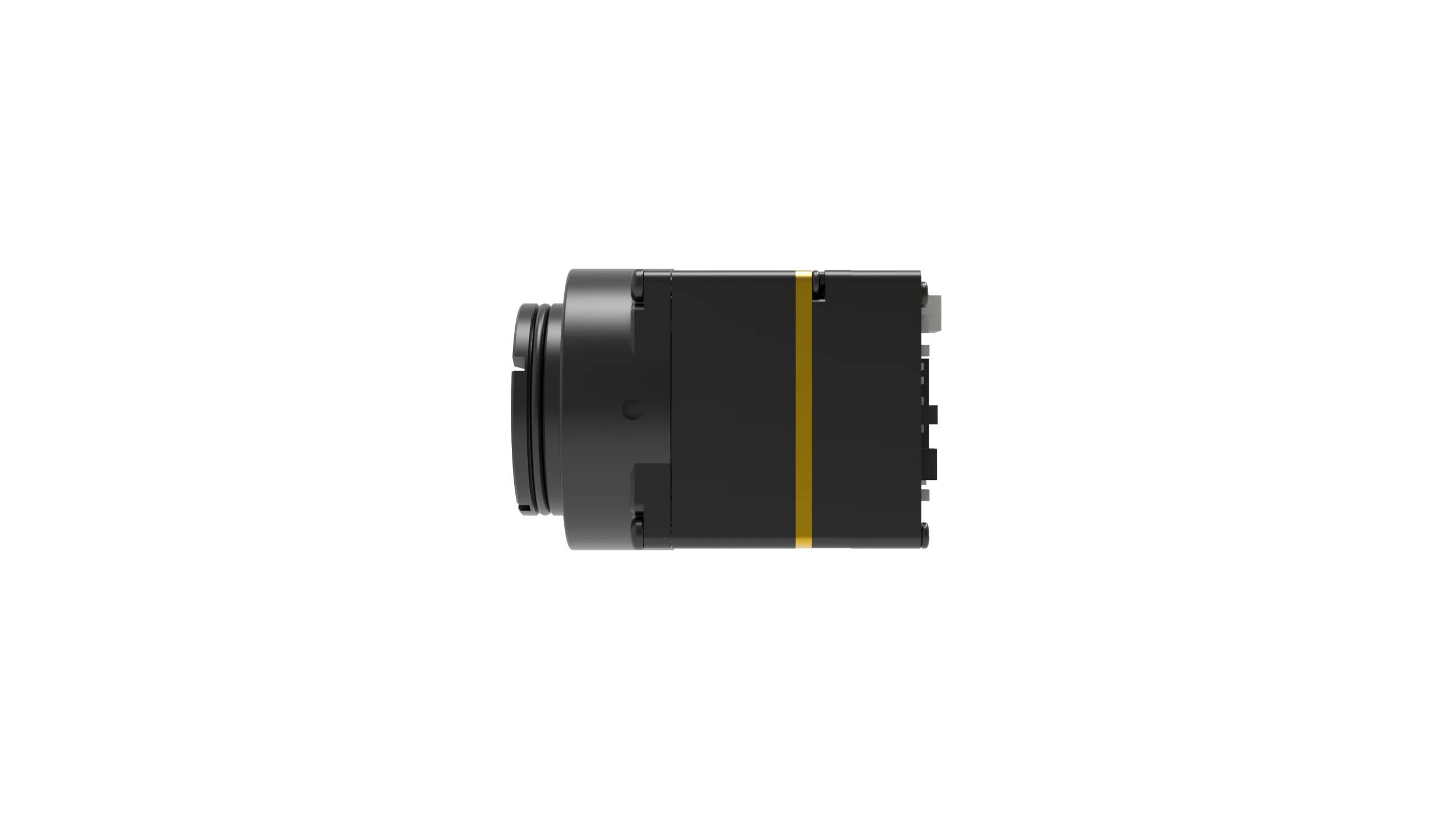
Table of Contents
- 👉 1. Infrared & EO Sensor Physics: LWIR vs. Visible Payloads in UAVs
- 👉 2. Onboard Edge Compute: 4 TOPS to 6 TOPS Edge AI Pipelines
- 👉 3. Flight Controller Interfacing: CRSF, MAVLink, and Low-Latency Control
- 👉 4. SWaP-C Optimization & Vibration Damping Engineering
- 👉 5. Hardware Comparison & Commercial Edge AI Vision Modules
- 👉 6. Step-by-Step OEM Integration & Flight Validation Protocol
- 👉 7. Deep-Dive Frequently Asked Questions (FAQ)
1. Infrared & EO Sensor Physics: LWIR vs. Visible Payloads in UAVs
Selecting an aerial imaging core starts with matching the spectral band to your operational flight profile. Vision payloads operate across two primary regimes: Long-Wave Infrared (LWIR, 8–14 µm) and the Visible/Near-Infrared spectrum (400–1000 nm). Each band presents distinct physical properties, optical manufacturing requirements, and computational demands.
The visible spectrum relies entirely on ambient photons bouncing off physical surfaces. Visible CMOS sensors provide dense pixel grids (such as 1080p, 2K, or 4K resolution), making them the natural choice for structural crack identification, optical character recognition on tail numbers, and daytime target feature classification. The downside? Visible cameras degrade fast in low-light environments, rain, heavy fog, smoke plumes, or back-lit high-contrast sun angles.
LWIR sensors detect passive blackbody thermal radiation emitted directly by matter above absolute zero, following Planck’s Law. Because LWIR cores read emitted heat rather than reflected light, an infrared UAV payload works in pitch-black conditions, cutting through camouflage, shadows, light tree canopies, and industrial haze. An onboard thermal detector isolates hot targets—such as human bodies, running internal combustion engines, transformer hotspots, or solar cell bypass diodes—against cool ambient backgrounds instantly.
Uncooled Microbolometers vs. Visible Sensor Arrays
For aerial platforms where grams and milliamps dictate flight time, uncooled thermal detectors are the standard choice. Cooled thermal imagers require cryogenic Stirling coolers running at liquid-nitrogen temperatures (77K). They offer incredible sensitivity, but they add immense weight, consume 10 to 30 watts, and require routine maintenance overhauls. Uncooled microbolometers operate at ambient temperatures, reducing size, weight, power, and cost (SWaP-C) while delivering robust field durability.
- ⚙️ Vanadium Oxide (VOx) Microbolometers: Modern thermal payloads favor VOx thin-film resistors over amorphous Silicon (a-Si) thanks to their higher Temperature Coefficient of Resistance (TCR) and significantly lower 1/f noise floors. When specifying a core for your payload, evaluate these key metrics:
- ⚙️ Noise Equivalent Temperature Difference (NETD): Measured in millikelvins (mK), NETD defines thermal sensitivity. A rating of sub-40 mK or sub-30 mK means the sensor picks up tiny fractional-degree temperature deltas during overcast days or thermal crossover windows when target and ambient background temperatures match.
- ⚙️ Pixel Pitch: Thermal detectors have moved from 17 µm to 12 µm and 8 µm pixel architectures. Dropping pixel pitch allows optical designers to build smaller, lighter Germanium lenses for a target focal length, cutting overall gimbal payload mass.
- ⚙️ Non-Uniformity Correction (NUC): Aircraft skin temperature fluctuations cause spatial drift across the microbolometer array. To maintain uniform radiometric output, thermal cores use internal mechanical shutter flags or advanced shutterless calibration algorithms running on the host processor.
- ⚙️ Visible Low-Light CMOS Sensors: Complementing thermal cores, modern 1/1.8-inch back-illuminated CMOS sensors deliver 60 Hz to 120 Hz frame rates with low-light sensitivity down to 0.001 lux. These visible sensors capture high-frequency structural edges, text markings, and spatial geometries that thermal sensors cannot resolve.
Optical Transmission and Mechanical Packaging
Standard optical crown glass blocks long-wave infrared radiation completely. Infrared UAV optics require specialized crystalline materials such as Germanium (Ge), Chalcogenide glass, or Silicon (Si) protected by Diamond-Like Carbon (DLC) anti-reflective coatings. Germanium provides high optical transmission across the 8–14 µm band, but it has high physical density and a large thermal refractive index drift. That means the lens barrel must incorporate passive mechanical athermalization to maintain sharp focal planes from -20°C up to +60°C.
Dual-sensor payloads combine a wide visible sensor alongside a thermal core, using picture-in-picture (PIP) modes or real-time pixel fusion. To see how these dual-band setups deploy across modern commercial airframes, take a look at our practical breakdown of drone thermal camera implementations.
2. Onboard Edge Compute: 4 TOPS to 6 TOPS Edge AI Pipelines
Traditionally, aerial payloads streamed analog composite or digital video over an RF link to a ground control station (GCS), where ground servers ran computer vision tracking. In real-world operations, RF downlinks introduce 100 ms to 300 ms of transport latency, digital compression blur, and complete tracking failure during line-of-sight dropouts or electronic interference. Running deep learning models directly on the airframe compute stack solves these issues.
The onboard edge vision pipeline pulls raw digital video frames over high-speed MIPI-CSI2 or DVP interfaces, pushes frames into an integrated Image Signal Processor (ISP) for hardware debayering and radiometric normalization, and transfers memory buffers into an embedded Neural Processing Unit (NPU). The NPU calculates target bounding boxes, classification confidence, and centroid pixel coordinates, sending low-latency control commands to the flight controller or gimbal motor drivers over a local serial bus.
Compute Sizing: TOPS, Precision, and Model Throughput
Edge AI compute hardware is rated by computational density in Tera-Operations Per Second (TOPS), operating under INT8 or FP16 precision:
- ⚙️ 4 TOPS Processing Stacks: A 4 TOPS INT8 processing engine strikes an efficient balance of thermal performance (drawing 3 to 5 W under full load) and high-speed inference for single-stream high-definition object detection. Running quantized convolutional neural networks (such as YOLOv8n, MobileNet-SSD, or lightweight anchor-free transformers), a 4 TOPS processor ingests 1080p or 2160×1440 video streams at 30 to 60 frames per second. This processing tier delivers sub-30 ms glass-to-inference latency and tracks up to 60 simultaneous targets.
- ⚙️ 6 TOPS Multi-Core Stacks: For fast airframes, interceptor drones, and dynamic multi-target visual scenes, a 6 TOPS processing node provides heterogeneous multi-core muscle (such as dual Arm Cortex-A76 cores paired with quad Cortex-A55 cores and a 6 TOPS NPU). This hardware handles high-frame-rate inputs (like 1080p @ 120 Hz) with inference times as low as 8 ms. These boards track up to 120 active objects while running lost-target kinematic recovery and optical flow estimation. Embedded spatial vision architectures, such as systems highlighted by Luxonis, show how tightly coupling sensor inputs with local edge AI accelerators maximizes system responsiveness.
Target Tracking and Lock Modes
Modern edge AI tracking engines execute deterministic spatial tracking algorithms directly in silicon:
- ✅ Reticle Locking: The operator designates a target using GCS crosshairs, and the processor matches scale-invariant feature transforms across consecutive frames using correlation filters.
- ✅ Close-to-Lock: The AI detector scans the visual field for classified classes (persons, vehicles, vessels) and automatically locks onto the target closest to the optical boresight.
- ✅ Lost-Target Recall & Kinematic Extrapolation: When a tracked vehicle or person disappears behind buildings, trees, or terrain, an embedded Kalman filter projects velocity vectors to maintain the expected bounding box, instantly re-acquiring lock when the target reappears.
3. Flight Controller Interfacing: CRSF, MAVLink, and Low-Latency Control
An edge AI vision payload must communicate directly with the drone’s autopilot to drive gimbal axes or command autonomous airframe tracking paths. Establishing a deterministic, high-baud-rate communication link between the vision module and the flight controller is vital for stable closed-loop flight control.
The system connects the edge AI module to the flight controller over a dedicated serial UART port. The vision processor tracks the target, calculates pixel error vectors from the optical center, and outputs rate commands to the autopilot. The flight controller updates the pan-tilt gimbal motors over PWM, CAN, or serial UART buses while sending telemetry and video overlays to the video transmitter.
Protocol Comparison: CRSF vs. MAVLink vs. S.Bus
- ⚙️ CRSF (Crossfire Protocol): Originally built for low-latency RC links, CRSF has become a go-to protocol for tight edge-vision tracking loops. Operating at baud rates from 115.2 kbps up to 416.6 kbps with lightweight bidirectional framing, CRSF lets the AI tracking engine inject tracking error offsets directly into autopilot channel overrides. Flight software like BetaFlight or PX4 Autopilot / ArduPilot parses CRSF streams with minimal CPU overhead, hitting update rates over 150 Hz.
- ⚙️ MAVLink (Micro Air Vehicle Link): For enterprise and defense payloads, MAVLink v2 over high-speed UART or Ethernet delivers structured messaging. MAVLink supports target GPS geolocation projection (fusing drone attitude, barometric altitude, laser rangefinder distance, and gimbal angles), system health monitoring, optical zoom commands, and standardized gimbal packets.
- ⚙️ S.Bus: While S.Bus remains common on legacy gimbal hardware, its unidirectional design and fixed 100 kbps inverted serial format make it less flexible for dynamic, bidirectional AI tracking workflows.
Control Loop Dynamics and Gimbal Coordination
When tracking a target, the edge AI processor calculates horizontal and vertical pixel errors relative to the optical center:
Error_X = X_target – X_center
Error_Y = Y_target – Y_center
The edge processor feeds these pixel error deltas into an internal Proportional-Integral-Derivative (PID) loop. The PID algorithm converts pixel offsets into angular rate commands (degrees per second). These commands stream to the gimbal controller or autopilot at 50 Hz to 120 Hz, continuously compensating for airframe buffeting, wind shear, and target motion to hold the target centered in the frame.
4. SWaP-C Optimization & Vibration Damping Engineering
Mounting high-compute edge AI processors alongside sensitive thermal and optical sensors inside compact airframes creates real Size, Weight, Power, and Cost (SWaP-C) challenges. Engineers must control both thermal dissipation and airframe vibration to protect optical alignment and maintain continuous compute stability.
The mechanical assembly mounts the optical core to a rigid boresight plate, routes processor heat through solid copper thermal planes into a CNC-machined aluminum housing, and isolates the entire payload from the airframe with tuned silicone dampers.
Thermal Dissipation in Enclosed Airframes
An edge AI module consuming 4 to 10 W inside a sealed carbon-fiber fuselage causes fast internal heat accumulation. In hot ambient air (+35°C to +45°C), junction temperatures on the NPU and CPU can cross safe operating limits (85°C to 105°C), causing thermal throttling that drops frame rates and breaks tracking loops.
- ⚙️ Conduction Cooling: Form direct conductive paths from the AI system-on-chip (SoC) and power management ICs (PMICs) using phase-change thermal interface materials (TIM) or high-conductivity thermal pads (6 to 12 W/m-K) linked to the module’s aluminum enclosure.
- ⚙️ Convection Airflow: On fixed-wing or forward-flight multirotors, integrate aerodynamic NACA ducts into the airframe shell. Direct incoming ram air across external heatsink fins to maintain stable thermal equilibrium during long flights.
Mechanical Resonance and Vibration Damping
Drone propulsion systems produce complex multi-axis vibration spectra. High-frequency motor harmonics (100 Hz to 500 Hz) combined with low-frequency propeller wash (15 Hz to 50 Hz) introduce mechanical noise into optical cores:
- ⚙️ Visible Rolling Shutter Artifacts: High-frequency vibrations pass directly into CMOS sensors, causing rolling shutter “jello” that distorts image frames and confuses AI feature tracking.
- ⚙️ Microbolometer Structural Integrity: While uncooled microbolometers do not suffer from rolling shutter artifacts, long-term vibration can fatigue detector wire bonds and misalign mechanical NUC shutter flags.
- ⚙️ Tuned Isolation Mounts: Mount the payload using 40-to-60 durometer silicone isolation dampers or compact wire-rope isolators. Keep the isolation system’s natural resonance frequency below 15 Hz to decouple motor and prop harmonics from the optics.
5. Hardware Comparison & Commercial Edge AI Vision Modules
Choosing edge AI hardware requires matching payload weight, optical field of view, compute density, and serial protocols to your airframe specifications. When sourcing vision cores for custom builds, review our comprehensive thermal camera OEM RFQ checklist to establish rigorous electrical and mechanical specifications before locking in designs.
The comparison below outlines two production-grade edge AI tracking modules built for direct integration into commercial, industrial, and defense UAVs.
4 TOPS HD UAV AI Tracking Module (TC01-HD)
The TC01-HD is an ultra-compact edge AI tracking module engineered for weight-sensitive UAV builds. Combining a 4 TOPS NPU compute stack with a wide-angle 1/1.8-inch optical camera, the TC01-HD provides onboard human and vehicle detection, tracking, picture-in-picture (PIP) display modes, and seamless flight controller integration via CRSF.
| Core Processing & AI Specifications | |
|---|---|
| Product Model | TC01-HD |
| AI Compute Density | 4 TOPS Edge NPU |
| Target Classes | Person and Vehicle |
| Detection Reference Distance | Vehicle: 800 m | Person: 300 m |
| Minimum Target Resolution | 10 x 10 pixels |
| Processing Latency | 30 ms reference |
| Dynamic Tracking Speed | Up to 140 km/h |
| Simultaneous Targets | Up to 60 targets |
| Display Modes | Picture-in-Picture (PIP) supported |
| Flight Control & Electrical Interface | |
| Autopilot Protocol | CRSF |
| Flight Controller Support | BetaFlight, PX4, and ArduPilot |
| Input Voltage Range | Regulated 9–16 V DC |
| Board Stack Dimensions | 38 x 38 x 24.5 mm |
| Mounting Pattern | 25.5 x 25.5 mm |
| Integrated EO Camera Sensor | |
| Optical Sensor Format | 1/1.8-inch CMOS |
| Focal Length & FOV | 4.37 mm (Diagonal 131.6° / Horizontal 109° / Vertical 57.5°) |
| Resolution & Max Framerate | 2160 x 1440 @ 60 Hz |
| Minimum Scene Illumination | 0.001 lux reference |
| Camera Head Size | 25.5 x 19.5 x 19.5 mm |
6 TOPS 1080p UAV AI Tracking Module (TM02-SOLO)
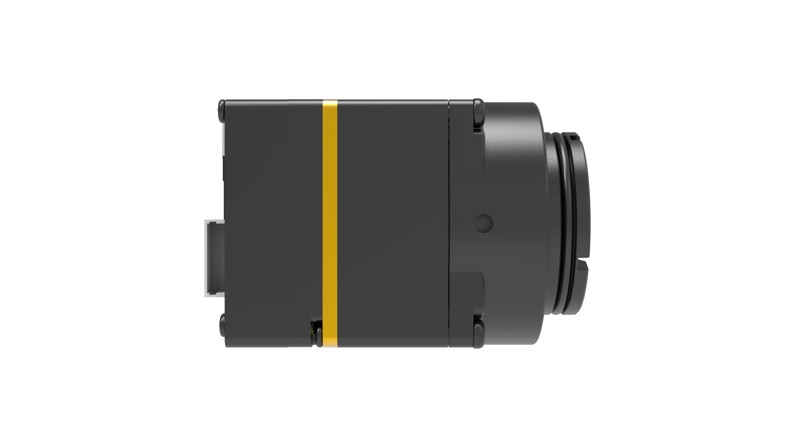
The TM02-SOLO is a high-throughput edge AI tracking module tailored for demanding high-speed interception, aerial tracking, and complex robotic applications. Powered by an advanced multi-core processor (dual Arm Cortex-A76 plus quad Cortex-A55) paired with a 6 TOPS NPU, the TM02-SOLO pairs with a 120 Hz low-light EO camera to deliver real-time multi-target tracking across speeds up to 450 km/h with an ultra-low 8 ms processing latency reference.
| Core Processing & AI Specifications | |
|---|---|
| Product Model | TM02-SOLO |
| CPU Architecture | Dual Arm Cortex-A76 @ 2.4 GHz + Quad Arm Cortex-A55 @ 1.8 GHz |
| AI Compute Density | 6 TOPS Edge NPU |
| Target Classes | Person and Vehicle |
| Detection Reference Distance | Vehicle: 400 m | Person: 170 m |
| Processing Latency | 8 ms supplier table reference |
| Dynamic Tracking Speed | Up to 450 km/h |
| Tracking Algorithms | Reticle locking, close-to-lock, route pre-map, lost-target recall, PIP |
| Simultaneous Targets | Up to 120 simultaneous tracks |
| Flight Control & Electrical Interface | |
| Control & Video Protocols | CRSF, UART, CVBS, Ethernet, and USB |
| Flight Controller Support | BetaFlight, PX4, and ArduPilot |
| Recommended Power Input | Regulated 9–16 V DC |
| Board Stack Dimensions | 45 x 45 x 26 mm |
| Mounting Pattern | 42.5 x 42.5 mm |
| Integrated EO Camera Sensor | |
| Optical Sensor Format | 1/1.8-inch Low-Light CMOS |
| Focal Length & FOV | 8.45 mm (Diagonal 66.3° / Horizontal 57.1° / Vertical 30.4°) |
| Resolution & Max Framerate | 1920 x 1080 @ 120 Hz |
| Minimum Scene Illumination | 0.001 lux reference |
| Camera Head Size | 25.5 x 19.5 x 19.5 mm |
For specialized payloads integrating long-range thermal scopes, bi-spectrum binoculars, or rugged handheld units, explore our broader catalog of field observation devices.
6. Step-by-Step OEM Integration & Flight Validation Protocol
Integrating an intelligent thermal or high-speed EO tracking core requires a structured bench-to-flight validation protocol to protect sensitive electronics, verify signal integrity, and validate tracking stability.
Follow these four testing phases before clearing your vision payload for autonomous flight operations:
Phase 1: Electrical Isolation and Power Rail Conditioning
- ⚙️ Transient Voltage Suppression: Never power edge compute boards directly from unbuffered LiPo/Li-Ion flight batteries. Active regenerative braking from Electronic Speed Controllers (ESCs) dumps inductive back-EMF voltage spikes exceeding 40 V onto the main DC bus. Always install a dedicated, high-efficiency DC-DC step-down buck regulator delivering a clean, regulated 9–16 V DC supply with peak-to-peak voltage ripple under 50 mV.
- ⚙️ Star-Grounding Topology: Wire power and ground in a strict star configuration. Connect camera sensor ground, AI compute ground, flight controller ground, and video transmitter ground to a single physical node to prevent ground loop currents from injecting noise into MIPI video data lines or serial telemetry streams.
Phase 2: Hardware-in-the-Loop (HIL) Simulation and Telemetry Mapping
- ⚙️ UART / CRSF Logic Matching: Confirm matching logic voltage levels (3.3V TTL vs. 5V tolerant pins) and baud rates between the AI module and the flight controller UART. Map RC transmitter auxiliary switches to handle target acquisition, lock toggle, PIP modes, and manual gimbal override.
- ⚙️ Glass-to-Actuation Latency Benchmarking: Measure total system response time on the bench. Point the vision sensor at an LED millisecond counter while recording gimbal motor movement with a high-speed camera. Verify that total latency—optical exposure, NPU inference, serial transmission, and gimbal PID loop actuation—stays well under 50 ms.
Phase 3: Static Motor-Thrust and EMI Validation
- ⚙️ EMC / EMI Radio Frequency Sweeps: Secure the fully assembled drone on a static thrust test stand. Run stepped throttle sweeps from 0% to 100% thrust while monitoring GPS carrier-to-noise ratio (CNR / SNR) and digital video link quality. Verify that high-speed NPU switching frequencies and DDR memory buses do not radiate electromagnetic noise into navigation antennas.
- ⚙️ Thermal Chamber Soak Test: Run the vision stack in continuous multi-target tracking mode for 45 minutes inside an unventilated +40°C chamber. Verify that SoC and NPU junction temperatures stabilize under 80°C with zero thermal throttling or dropped frames.
Phase 4: Controlled Flight Trials and Tracking Envelope Verification
- ⚙️ Optical Standoff Range Confirmation: Fly test patterns at 50 m, 150 m, 300 m, and 500 m Above Ground Level (AGL). Document target acquisition success rates against human and vehicular targets across different approach angles, ground clutter, and solar angles.
- ⚙️ Failsafe Occlusion Testing: Intentionally obscure tracked targets behind buildings or tree lines. Verify that the tracking engine transitions smoothly into its lost-target recall state, projects motion vectors using Kalman filtering, and re-engages lock instantly when the target clears the obstruction.
7. Deep-Dive Frequently Asked Questions (FAQ)
How should I interface an infrared camera core with UAV flight controllers like ArduPilot, PX4, or BetaFlight?
What is the primary trade-off between raw thermal sensor streaming and onboard edge AI tracking for UAVs?
What thermal sensor resolution and optical focal length are recommended for standard infrared UAV surveillance?
How do environmental factors such as thermal crossover and rain impact infrared UAV detection performance?
📚 References & Further Reading
- Industry Standard: Explore open-source autonomous flight architectures and control standards via the PX4 Autopilot Ecosystem.
- Industry Standard: Review embedded spatial AI and computer vision acceleration principles at Luxonis Spatial AI Solutions.
- Related Guide: Read our operational analysis of multi-spectral aerial payloads in our Drone Thermal Camera Integration Guide.
- Related Guide: Review our system engineer’s procurement checklist: Thermal Camera Suppliers OEM RFQ Checklist.
- Related Guide: Browse rugged tactical and commercial imaging devices in our Field Observation Devices Catalog.