Thermal Master P1 Review: Technical Specs, Limitations, and OEM Alternatives
Thermal Master P1 Review: Technical Specs, Limitations, and OEM Alternatives
The flood of low-cost, miniature long-wave infrared (LWIR) imagers has completely changed how field technicians, tinkerers, and benchtop techs handle temperature spot-checks. The thermal master p1 carved out a solid niche here: an ultra-compact, smartphone-tethered dongle built for quick diagnostic sweeps over USB-C. By leaning on your phone’s processor and display, it gives hobbyists and home inspectors an affordable window into basic thermal troubleshooting without having to drop thousands on dedicated inspection gear.
Here’s the deal, though: if you’re a payload engineer, machine vision integrator, or robotics architect, you’re playing an entirely different ballgame. Consumer thermal dongles come with massive design trade-offs that kill their utility in serious deployments: wild latency spikes, fragile USB-C plugs, locked-down mobile apps, background telemetry leaks, and uncalibrated add-on optics. When you move from casual handheld scanning to mission-critical UAV gimbals, inline automated PCB thermal inspection, or autonomous mobile robotics, you can’t rely on a phone accessory. You need bare-board or modular OEM thermal camera cores that output clean, low-latency digital video over MIPI CSI-2, BT.656, or native UVC while meeting strict SWaP (Size, Weight, and Power) budgets.
Table of Contents
- 👉 1. Thermal Master P1: Architecture and Technical Baseline
- 👉 2. Critical Bottlenecks of Consumer Thermal Dongles in Industrial Environments
- 👉 3. Architectural Shift: Embedded OEM Thermal Camera Cores
- 👉 4. Real-World Specifications: Consumer Dongle vs. CAMCUDA OEM Modules
- 👉 5. Integration Pathways: Thermal Diagnostics, UAV Gimbals, and Low-SWaP Robotics
- 👉 6. Compliance, Security, and Procurement Best Practices
- 👉 7. Frequently Asked Questions (Deep-Dive Engineering FAQ)
1. Thermal Master P1: Architecture and Technical Baseline
Look at the thermal master p1 and you see the classic blueprint for mass-market microbolometer gadgets. Housed in a tiny aluminum shell with a fixed USB Type-C plug, it’s built purely as a peripheral for Android phones, tablets, and Windows machines running companion viewing software. The hardware itself offloads almost every complex image task to the host CPU, including raw frame synchronization, non-uniformity correction (NUC) calculations, and false-color lookup table (LUT) rendering.
At the silicon level, the module packs an uncooled Vanadium Oxide (VOx) or Amorphous Silicon (a-Si) focal plane array (FPA) tuned to the standard 8 to 14 micrometer long-wave infrared (LWIR) atmospheric band. When infrared light hits the suspended microbolometer membrane, the tiny temperature rise shifts the material’s electrical resistance. An on-die Readout Integrated Circuit (ROIC) reads that resistance shift, digitizes the signals, and streams raw counts or semi-calibrated radiometric frames across the USB bus.
The optics use a miniature Germanium or Chalcogenide glass lens fixed at a wide hyperfocal setting (roughly 0.2 meters out to infinity), which means there’s no mechanical focus ring to mess with. It draws operating power straight off the host device’s USB On-The-Go (OTG) rail, burning anywhere between 0.8 W and 1.2 W depending on sensor die temperature, polling rates, and backend processing loads.
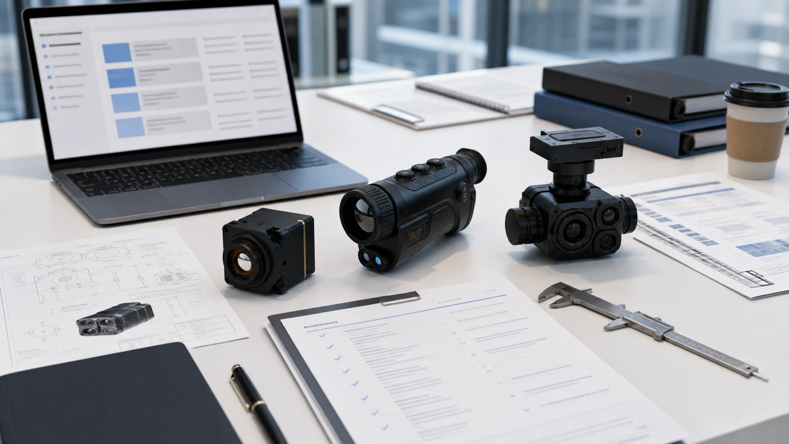
In the shop or out on a residential HVAC call, this setup gets the job done for quick surface checks. But the minute you try sticking it onto an automated test bench or a drone frame, the cracks start showing. Because the heavy processing happens in the user-space layer of a mobile operating system, unpredictable thread scheduling creates jitter and dropped frames. You simply cannot build reliable closed-loop automation, target tracking, or robotic vision when your video stream is running on unpredictable mobile software cycles.
2. Critical Bottlenecks of Consumer Thermal Dongles in Industrial Environments
When you try integrating smartphone-style thermal dongles into industrial automation, defense sub-assemblies, or autonomous flight platforms, you immediately run into severe physical, optical, and architectural roadblocks.
Mechanical & Physical Interconnect Vulnerability
That rigid male USB-C plug is designed for gentle, occasional manual insertion into a phone port. In an industrial setup or on a multi-rotor drone dealing with continuous motor vibration and structural harmonics, that rigid plug turns into a direct lever arm. It concentrates constant torsional and shear stress right onto the receptacle’s surface-mount solder pads. Over hundreds of operating hours, cyclic fatigue causes intermittent communication dropouts, frozen frames, and ripped PCB pads. Industrial payloads demand rugged locking board-to-board headers (like the Hirose DF40 family) or direct-soldered wire harnesses.
Optical Limitations & The “DIY Macro Lens” Pitfall
Engineers often try to use these fixed-focus dongles for close-up PCB thermal troubleshooting by 3D-printing snap-on rings to hold cheap Zinc Selenide (ZnSe) CO2 laser lenses in front of the factory optic. While it lets you focus on small IC packages, it wrecks your radiometric calibration in three distinct ways:
- ⚙️ Uncalibrated Transmission Losses: Adding third-party optical elements introduces raw antireflective (AR) coating transmission losses (often 3% to 8%), causing the internal temperature calculation algorithm to skew readings lower than reality.
- ⚙️ Field Curvature & Vignetting: Non-matched auxiliary optics create barrel distortion and peripheral cosine-fourth irradiance drop-off, throwing off temperature measurements near the outer edges of the board.
- ⚙️ Modulation Transfer Function (MTF) Breakdown: Blurring across spatial frequencies destroys the camera’s true Instantaneous Field of View (IFOV). Precision machine vision built around the EMVA 1288 Standard demands fully characterized, factory-matched athermal optics.
Software, Latency, and Cloud Security Vulnerabilities
Consumer thermal dongles depend entirely on consumer mobile apps. These applications often require broad device permissions—network access, location data, local storage—and quietly run telemetry packages in the background. In secure aerospace facilities, defense research labs, and cleanroom test environments, running an active camera through a third-party app with network access is an immediate security red flag. On top of that, non-real-time mobile OS rendering introduces 150+ milliseconds of display lag, making tight visual tracking and real-time obstacle avoidance impossible, as detailed across modern ArXiv Computer Vision papers.
3. Architectural Shift: Embedded OEM Thermal Camera Cores
If you’re building a real embedded system, you need to dump consumer gadgets and move to dedicated OEM thermal camera cores. An industrial OEM module gives you bare-metal detector access, standardized interfaces, absolute determinism, and ruggedized mounting footprints designed for integration.
In a true OEM thermal core, the optical train, microbolometer sensor array, onboard DSP/FPGA, and interface electronics form a tightly integrated, vibration-resistant engine. The onboard processor handles all the critical low-level heavy lifting—Non-Uniformity Correction (NUC), Bad Pixel Replacement (BPR), dynamic range compression, and Digital Detail Enhancement (DDE)—directly in hardware before sending the video out.
Low-SWaP Optimization (Size, Weight, and Power)
Industrial OEM cores strip away all the non-essential plastic, battery housing, and display fluff to hit minimum Size, Weight, and Power (SWaP) targets. High-end sub-assembly cores weigh less than 20 grams—or even under 3.5 grams for micro-die variants. That kind of weight profile lets you drop thermal vision directly into balanced dual-axis drone gimbals without overloading small brushless motors or draining your flight pack.
Direct Bus Integration: MIPI CSI-2, LVCMOS, and Native UVC
Instead of wrestling with closed, proprietary USB software layers, OEM modules feed straight into standard embedded video pipelines:
- ✅ MIPI CSI-2 (2-Lane): Feeds raw frames straight into the Image Signal Processor (ISP) of embedded system-on-modules like NVIDIA Jetson, NXP i.MX8, or Rockchip platforms, keeping frame capture latencies in the single-digit milliseconds.
- ✅ Parallel LVCMOS / BT.656: Perfect for hardware integrators piping video straight into an FPGA for custom hardware filtering, edge detection, or multispectral sensor fusion.
- ✅ Direct UVC USB: Standard, driver-free video classes that register natively in Linux (V4L2), ROS/ROS2, and industrial Windows runtimes without any closed companion apps.
4. Real-World Specifications: Consumer Dongle vs. CAMCUDA OEM Modules
Here is how standard consumer dongle architecture (like the thermal master p1 baseline) stacks up against dedicated, integration-grade OEM modules like the payload-ready CAMCUDA AeroMini 640 and the ultra-compact CAMCUDA SuperMini 640 / 640T.
| Engineering Parameter | Thermal Master P1 (Consumer Baseline) | CAMCUDA AeroMini 640 | CAMCUDA SuperMini 640 / 640T |
|---|---|---|---|
| Target Application | Handheld Consumer / Mobile Tech | UAV Payloads / Gimbal Systems / Robotics | Space-Constrained Micro-UAVs / Low-SWaP Systems |
| Detector Type | Uncooled VOx / a-Si Microbolometer | Uncooled VOx Microbolometer | Uncooled VOx Microbolometer |
| Native Resolution | Entry Grade (up to 256×192) | 640 × 512 | 640 × 512 |
| Pixel Pitch | 12 μm | 12 μm | 8 μm Ultra-High Density |
| Spectral Response | 8–14 μm | 8–14 μm | 8–14 μm |
| Thermal Sensitivity (NETD) | ≤50 mK to ≤60 mK | ≤50 mK (Standard) / ≤40 mK (Optional) | ≤40 mK @ 25 °C, F1.0 |
| Frame Rate Options | Typ. 25 Hz (App Limited) | 60 Hz Default / 30 Hz Factory / 25 Hz Radiometric | 50 Hz (640 Imaging) / 30 Hz (640T Radiometric) |
| Core Dimensions | Dongle shell (~45 × 25 × 15 mm) | 21 × 21 × 28 mm (without lens/flange) | 13 × 13 × 13.4 mm (bare core) |
| Core Weight | ~25 to 40 g (integrated shell) | <20 g (without lens/flange) | <3.5 g (bare core) |
| Video / Data Interfaces | Fixed Male USB-C Plug | YUV, USB, BT.656, CVBS (PAL/NTSC) | 8-bit LVCMOS / BT.656, 2-Lane MIPI, 4-Pin USB |
| Control Interface | Proprietary Mobile Driver | UART, RS232, RS422 | UART (1.8 V logic) |
| Power Consumption | 0.8 W – 1.2 W (5 V USB) | <0.5 W (Typical at 25 °C) | ≤0.5 W (Typical core power) |
| Lens Options | Fixed focus hyperfocal | 4, 7, 9, 13, 15, 18, 25, 35, 50 mm | 3.7 mm, 6.1 mm, 8.7 mm, 11 mm (F1.0 Athermal) |
| Operating Temperature | 0 °C to +40 °C | −40 °C to +80 °C | −40 °C to +80 °C |
CAMCUDA AeroMini 640: Comprehensive OEM UAV Showcase
The CAMCUDA AeroMini 640 is built from the ground up for drone airframes, stabilized pan-tilt-zoom (PTZ) gimbals, and automated outdoor inspection stations. It packs a 640 × 512 uncooled VOx focal plane array at a 12 μm pixel pitch, giving you clean resolution while pulling less than 0.5 W of power. The core module weighs under 20 grams (stripped of lens and flange) with compact dimensions of 21 × 21 × 28 mm.
| AeroMini Parameter | Factory Specification | Integration Notes |
|---|---|---|
| Thermal Resolution | 640 × 512 VOx | Uncooled focal plane detector |
| Frame Rates | 60 Hz default / 30 Hz option / 25 Hz radiometric | High-speed non-radiometric default is 60 Hz |
| Sensitivity (NETD) | ≤50 mK (≤40 mK optional) at 25 °C, F/1.0 | Enables fine thermal gradient discrimination |
| Digital Video Out | YUV, USB, BT.656 | Board and firmware dependent |
| Analog Video Out | CVBS (PAL / NTSC) | For analog FPV and legacy telemetry links |
| Command Bus | UART, RS232, RS422 | Direct gimbal controller and autopilot integration |
| Supply Voltage | 5 V or 12 V (Interface board dependent) | Do not connect 5 V input pins to 12 V rails |
| Radiometric Range | −20 °C to +550 °C | Available on radiometric factory build |
You can equip the AeroMini with a massive range of factory-characterized optics depending on your operational envelope: 4 mm (100° × 82° FOV), 7 mm (64° × 52° FOV), 9 mm (48.7° × 38.6° FOV), 13 mm (31.9° × 25.7° FOV), 15 mm (29.3° × 23.5° FOV), 18 mm (24.2° × 19.5° FOV), 25 mm (17.5° × 14° FOV), 35 mm (12.5° × 10° FOV), or 50 mm (8.8° × 7° FOV).
View Product Details & Pricing ➔
CAMCUDA SuperMini 640 / 640T: Ultra-Light Low-SWaP Module
The CAMCUDA SuperMini 640 / 640T sets a serious benchmark in extreme SWaP optimization. Packing a cutting-edge 8 μm pixel pitch microbolometer, the bare core measures an astonishing 13 × 13 × 13.4 mm and weighs under 3.5 grams. The module ships in two targeted hardware flavors:
- ✅ CAMCUDA SuperMini 640 (Imaging Variant): Runs at 50 Hz, outputting 8-bit LVCMOS / BT.656 and 2-lane MIPI interfaces tuned specifically for ultra-low latency targeting and robotic navigation.
- ✅ CAMCUDA SuperMini 640T (Thermographic Variant): Runs at 30 Hz, delivering full pixel-by-pixel radiometric temperature measurement across dual calibrated spans (−20 °C to +150 °C and +100 °C to +650 °C) over CDS3 and MIPI data streams.
| Electrical / Signal Path | Published Engineering Requirement | Hardware Integration Rule |
|---|---|---|
| MAIN_POWER Rail | 3.8–5.2 V (Typical 5 V) | 10 mV peak-to-peak maximum noise |
| +3.3 V Power Rail | 3.28–3.32 V | 10 mV peak-to-peak maximum ripple |
| +1.8 V Power Rail | 1.78–1.82 V | 1 mV RMS maximum noise (1 Hz–50 kHz) |
| Interconnect Header | Hirose DF40C-30DP-0.4V(51) 30-Pin | Direct board-to-board high-reliability mating |
| Digital Video Bus | 8-bit LVCMOS or 2-lane MIPI | BT656 on 640; CDS3 on 640T (Non-simultaneous) |
| Expansion Option | TMS6102V100F022 Expansion Board | Provides 4-pin USB connection for both variants |
The SuperMini uses custom F1.0 athermalized lenses matched to the tight 8 μm pixel pitch: 3.7 mm (90.0° × 68.2° FOV, 2.16 mrad IFOV), 6.1 mm (46.6° × 37.6° FOV, 1.31 mrad IFOV), 8.7 mm (40.0° × 32.2° FOV, 0.92 mrad IFOV), and 11 mm (24.9° × 20.0° FOV, 0.73 mrad IFOV).
View Product Details & Pricing ➔
5. Integration Pathways: Thermal Diagnostics, UAV Gimbals, and Low-SWaP Robotics
Building an integrated thermal vision payload means crunching your optical math, designing clean power rails, and keeping structural vibration under control.
Optical Selection & IFOV Calculations for Precision Tasks
Whether you’re debugging dense circuit boards or hunting hot spots from a drone, resolving fine features over distance comes down to your Instantaneous Field of View (IFOV). In simple terms, IFOV is the exact angle covered by a single pixel:
IFOV (mrad) = [ Pixel Pitch (μm) / Focal Length (mm) ]
In the shop doing component-level PCB failure analysis, an 8 μm pitch core like the CAMCUDA SuperMini 640 paired with an 11 mm lens yields an IFOV of 0.73 mrad. Position that module 15 cm above a board under test, and each pixel resolves a spot size of roughly 0.11 mm. That lets you pinpoint shorted 0402 surface-mount capacitors, hot traces, and localized die overheating without clipping uncalibrated macro lenses over your sensor.
For aerial search and perimeter security, an AeroMini 640 running an 18 mm or 35 mm lens drops your field of view down to a focused 12.5° × 10°, allowing clean human target detection and hotspot tracking from hundreds of meters away.
Thermal Drift Management and Power Integrity
Uncooled microbolometers are highly sensitive to thermal drift caused by ambient shifts and board-level heat soak. Consumer dongles try to handle this with clunky app-level NUC cycles that freeze the frame randomly. Industrial OEM cores use hardware-timed mechanical shutters paired with on-die temperature sensor lookup tables for smooth, predictable calibration.
Clean power is non-negotiable. The CAMCUDA SuperMini series requires that the +1.8 V core supply rail keep noise strictly under 1 mV RMS (from 1 Hz to 50 kHz), while keeping the 5 V rail under 10 mV peak-to-peak ripple. If your power supply is noisy, you’ll see horizontal banding artifacts across the image, destroying your NETD sensitivity across its −40 °C to +80 °C operating range.
6. Compliance, Security, and Procurement Best Practices
When selecting thermal imaging components for commercial gear, defense sub-assemblies, or utility inspection systems, supply chain transparency and regulatory compliance make or break a project.
Supply Chain Traceability & NDAA Conformance
Consumer dongles picked up from e-commerce storefronts come with opaque component histories, proprietary ASICs, and untraceable software builds. If you’re building systems for North American or NATO-aligned commercial and defense contracts, full NDAA conformance is mandatory. Integrators should review structured documentation, such as the NDAA thermal camera module North America RFQ documents, before locking down a component vendor.
Integration Support & Product Lifecycles
Consumer gadgets live on short 6-to-12-month commercial lifecycles. Once the manufacturer drops a model, you get unannounced board revs, driver breaks, or outright product discontinuation. Industrial OEM modules provide long-term stability:
- ✅ Multi-year hardware availability with strict, locked Bill of Materials (BOM) lifecycles.
- ✅ Comprehensive hardware integration sheets covering power ripple tolerances, Hirose 30-pin DF40C pinouts, and register-level serial commands.
- ✅ Dedicated engineering resources, like the CAMCUDA Support Hub, for low-level SDK and kernel driver integration.
7. Frequently Asked Questions (Deep-Dive Engineering FAQ)
Can you use the Thermal Master P1 without third-party app privacy risks?
How do you add macro focus to a Thermal Master P1 for close-up PCB inspection?
Why upgrade from a USB-C smartphone dongle to an OEM thermal imaging core?
📚 References & Further Reading
- Industry Standard: EMVA 1288 Standard for Vision Sensor & Camera Characterization
- Computer Vision Research: ArXiv Computer Vision Research Repository
- Related Guide: NDAA Thermal Camera Module North America RFQ Documentation Guide
- Support Hub: CAMCUDA Technical Integration Support & FAQ Hub
- Product Datasheet: CAMCUDA AeroMini 640 UAV Thermal Camera Core
- Product Datasheet: CAMCUDA SuperMini 640 / 640T Ultra-Light LWIR Core