Thermal Drone News: 640 LWIR Sensor Trends, Edge AI Tracking & OEM Payload Design
Thermal Drone News: 640 LWIR Sensor Trends, Edge AI Tracking & OEM Payload Design
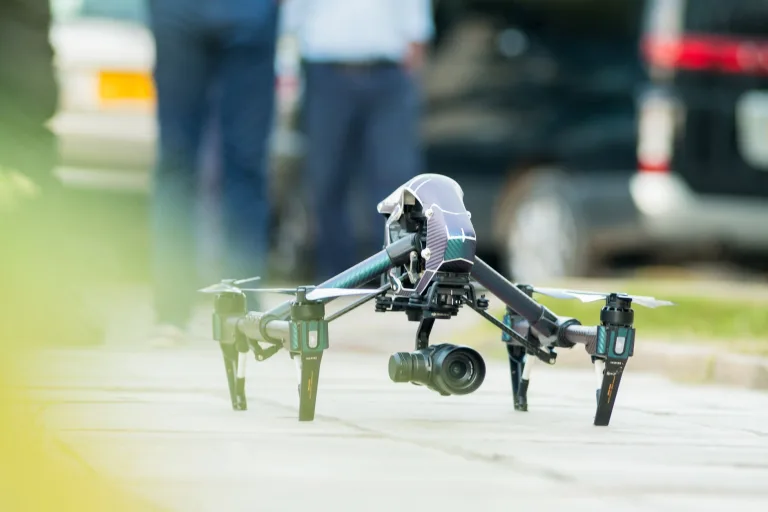
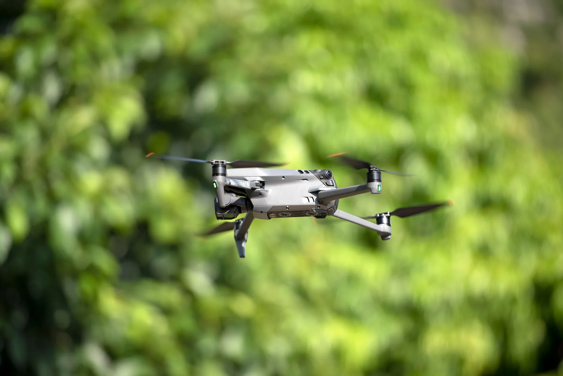
Look at the unmanned aerial vehicle (UAV) market today, and you will see a massive architectural shift taking place on the workbench. For years, enterprise drone programs and defense contractors were backed into a corner by closed, proprietary aircraft. You bought a complete turnkey rig with a locked flight stack, proprietary video transmission, and a factory-sealed optical payload. When you wanted to tweak the telemetry pipeline, swap out an optical element, or bypass cloud-sync restrictions, you hit a brick wall. In the shop, we call that the golden cage. Today, payload engineers are breaking out of it.
Here’s the deal: modern search and rescue (SAR), tactical ISR, and critical utility inspection programs demand modular, open-interface Long-Wave Infrared (LWIR) payloads. System architects are building their own 2-axis and 3-axis micro-gimbals around uncooled 640×512 Vanadium Oxide (VOx) thermal cores. These high-resolution sensors deliver the raw spatial detail and low thermal noise needed to pick out human heat signatures through dense forest canopy or flag sub-degree anomalies on a 500 kV transformer bank from well over 100 meters Above Ground Level (AGL).
Pulling off a reliable airborne thermal setup takes real systems engineering. You cannot just slap an infrared sensor into a 3D-printed housing and expect clean tracking at 50 knots. You have to balance Size, Weight, and Power (SWaP) constraints, manage optical Modulation Transfer Functions (MTF), isolate low-noise analog traces from noisy brushless motor switching, and pull heat out of sealed carbon-fiber pods. Let’s break down the sensor physics, edge AI tracking workflows, interface trade-offs, and optical calculations shaping next-generation thermal drone payloads.
Table of Contents
- 👉 1. Thermal Drone News: The Shift to Open-Architecture LWIR Payloads
- 👉 2. 640×512 Sensor Physics: 12 µm Pitch, NETD ≤40 mK, and Thermal Sensitivity
- 👉 3. Edge AI Computer Vision: Real-Time Target Tracking on Thermal Streams
- 👉 4. Payload Architecture: Digital (USB/BT.656) vs. Ultra-Low-Latency Analog (CVBS) Pipelines
- 👉 5. 60 Hz Non-Radiometric Video vs. 25 Hz Calibrated Radiometric Measurement
- 👉 6. OEM Thermal Core Deep-Dive: AeroMini 640 vs. W640-TIF-K1
- 👉 7. Optics Selection & Johnson’s Criteria Range Modeling for UAV Gimbals
- 👉 8. Mechanical, Thermal & Electrical Integration Guidelines for Drone Payloads
- 👉 9. Thermal Drone News & Payload Engineering FAQ
1. Thermal Drone News: The Shift to Open-Architecture LWIR Payloads
If you have been watching the aerial robotics landscape over the past two years, you know the days of being locked into a single foreign vendor’s ecosystem are fading fast. Industrial fleet managers and defense contractors ran headfirst into software geo-fencing, proprietary battery protocols, and zero-day supply chain freezes. If a camera failed in the field, you could not just swap a board; you had to ship the whole aircraft back through a multi-month RMA pipeline.
Engineering teams are responding by building their own modular front-ends around bare OEM drone camera subsystems. By integrating standalone uncooled Long-Wave Infrared (LWIR) cores into custom airborne gimbals, integrators gain four decisive advantages:
- ✅ Supply-Chain Sovereignty: You control the bill of materials. When you source core thermal engines independently, your production timeline is not held hostage by proprietary airframe redesigns or sudden policy shifts.
- ✅ Zero-Latency Direct Signal Routing: Off-the-shelf consumer drones pass video through three or four compression layers before it hits your screen. By pulling raw digital or direct analog video off the core, you feed your companion computer or video transmitter with zero intermediary buffer delay.
- ✅ Aggressive SWaP-C Optimization: Stripping away bulky plastic housings, redundant internal batteries, and consumer-grade trinkets can drop payload mass by 40% to 60%. On a mid-size quadcopter, shedding 150 grams translates directly into 6 to 9 minutes of extra loiter time over the target area.
- ✅ Native Open-Source Flight Control: Standard serial control over UART, RS232, or RS422 lets you talk directly to autopilots running PX4 or ArduPilot via standard MAVLink telemetry, keeping ground station control predictable and transparent.
This movement has made military-grade 640×512 thermal imaging viable across commercial operations, from midnight search-and-rescue runs in mountain terrain to autonomous pipeline surveys.
2. 640×512 Sensor Physics: 12 µm Pitch, NETD ≤40 mK, and Thermal Sensitivity
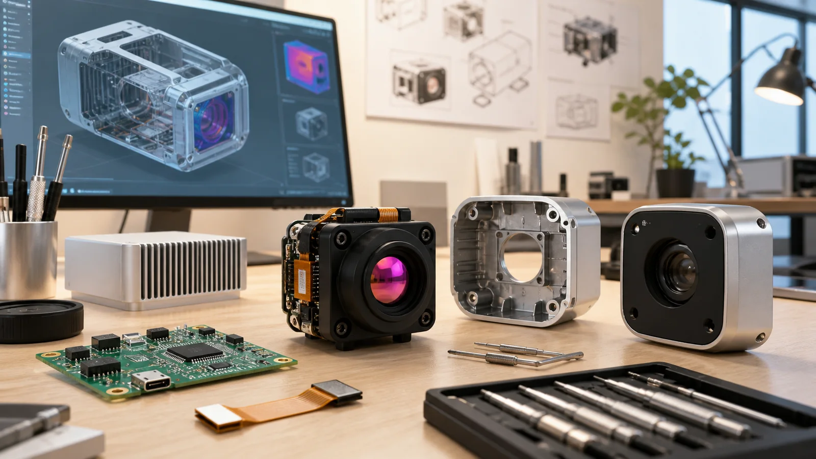
Let’s get into the detector physics. An uncooled Long-Wave Infrared microbolometer is essentially an array of microscopic thermistors suspended over a silicon substrate. It captures radiation in the 8 to 14 micrometer spectrum—the atmospheric transmission window where ambient-temperature objects radiate most of their thermal energy.
The imaging chain starts at the Germanium optical element. Incoming infrared energy passes through the lens and strikes a suspended thin-film membrane. The absorbed thermal radiation heats the membrane, changing its electrical resistance. An underlying Readout Integrated Circuit (ROIC) scans each pixel across the 640×512 array, converts those minute resistance variations into electrical voltages, digitizes the signals, and pushes the data to an onboard digital signal processor (DSP) for real-time Non-Uniformity Correction (NUC).
Vanadium Oxide (VOx) vs. Amorphous Silicon (a-Si)
In thermal drone gimbals, Vanadium Oxide (VOx) has effectively won the battle against Amorphous Silicon (a-Si). In the field, the differences are obvious:
- ⚙️ Higher TCR (Temperature Coefficient of Resistance): VOx delivers a significantly higher change in resistance per degree of temperature shift, yielding better dynamic contrast.
- ⚙️ Lower 1/f Electrical Noise: VOx arrays show cleaner thermal baselines, which means fewer noisy salt-and-pepper artifacts in uniform thermal scenes like calm open water or clear skies.
- ⚙️ Faster Thermal Time Constants: VOx membranes heat and cool rapidly, preventing ghosting and smearing during fast drone yaw maneuvers or aggressive gimbal repositioning.
The Real-World Impact of 12 µm Pixel Pitch
The industry standard has migrated from legacy 17 µm and 25 µm nodes down to 12 µm. From a mechanical and optical standpoint, that pixel shrink changes everything on a drone:
- ✅ Smaller Germanium Glass: Because the active sensor area is physically smaller (roughly 7.68 × 6.14 mm for a 640 array at 12 µm), you need a much shorter focal length to achieve the exact same field of view compared to a 17 µm sensor.
- ✅ Weight Savings on the Gimbal: Germanium is heavy, dense glass. Shrinking the optical diameter drops significant front-end mass, directly reducing the rotational inertia of the gimbal.
- ✅ Lower Motor Torque Demands: With less inertia on the pitch and roll axes, you can downsize your brushless gimbal motors, cut operating current, and eliminate high-frequency motor oscillations in windy conditions.
Demystifying NETD (Noise Equivalent Temperature Difference)
NETD is the metric that separates cheap thermal novelty toys from serious industrial tools. Measured in millikelvins (mK), it tells you the smallest temperature difference the sensor can resolve before the signal gets buried in internal electronic noise floor:
- ⚙️ NETD ≤50 mK (Industrial Baseline): Solid for standard solar farm scans or roof moisture surveys where thermal deltas run 5 °C to 20 °C above ambient.
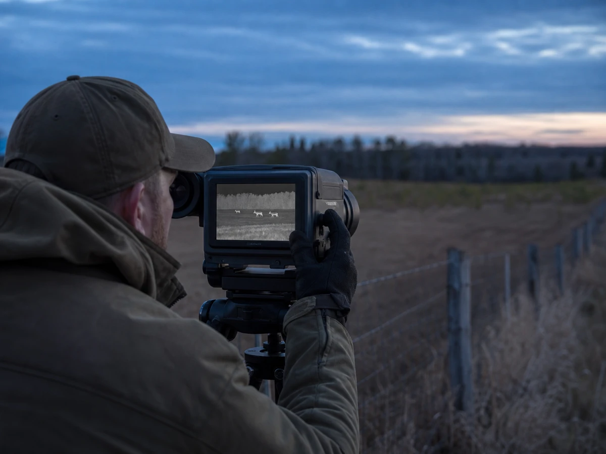
- ⚙️ NETD ≤40 mK (High-Sensitivity Tier): Essential for low-delta thermal environments. Think of maritime search and rescue on cold open water, early-morning sweeps over damp ground, or flying through light fog. When a lost hiker’s thermal signature is separated from wet terrain by just 0.4 °C, an NETD ≤40 mK core pulls clean edge contours where a cheaper sensor shows muddy gray noise.
3. Edge AI Computer Vision: Real-Time Target Tracking on Thermal Streams
Let’s look at how modern thermal feeds are actually used. Flying a drone while staring at a handheld screen and manually tracking a target with gimbal thumbsticks is exhausting, error-prone, and unsustainable on long missions. Modern tactical and industrial payloads push the thermal stream straight into an onboard edge AI processor mounted right inside the aircraft fuselage.
In a typical edge AI setup, the thermal core streams raw digital frames over USB or parallel buses into an embedded companion processor—like an NVIDIA Jetson Orin Nano, Xavier NX, or an onboard neural accelerator. The compute node pulls frames using native Video4Linux2 (V4L2) drivers with zero-copy memory access. The pipeline runs Contrast Limited Adaptive Histogram Equalization (CLAHE) to boost local thermal contrast, feeds the frames into a TensorRT-optimized deep neural network (such as YOLOv8 or RT-DETR), and hands bounding boxes to a spatial tracker like ByteTrack. From there, a control node converts target pixel offsets into MAVLink MOUNT_CONTROL commands, steering the gimbal motors to lock the target dead center.
Thermal Infrared AI: Strengths and Pitfalls
Working with thermal feeds for computer vision is a different ballgame compared to standard RGB video:
- ✅ Total Illumination Invariance: Thermal sensors do not care if it is pitch black, glaring midday sun, or backlit by headlights. The network gets identical shape and heat boundaries day and night.
- ⚠️ Lack of Chromatic Cues: Standard neural networks trained on visible RGB datasets (like COCO) fail on thermal feeds because there are no color channels. Models must be trained or fine-tuned on raw LWIR imagery, relying on heat gradients, aspect ratios, and spatial textures.
- ⚠️ Dynamic Range Swings: When an aircraft pans from cold open sky down to hot asphalt, the global histogram shifts radically. You need aggressive dynamic range compression (DRC) and localized normalization so targets do not bloom out or vanish into the floor.
ROS 2 Middleware Integration
For autonomous robotics teams, standardizing on open robotics frameworks is standard practice. Integrators pipe the thermal camera feed into a ROS 2 node using standard image transport pipelines documented in the ROS 2 Documentation. The node handles frame ingestion, model inference, and target state estimation, then publishes gimbal rate commands over serial MAVLink to the autopilot, closing the tracking loop onboard without human intervention.
4. Payload Architecture: Digital (USB/BT.656) vs. Ultra-Low-Latency Analog (CVBS) Pipelines
When you sit down to design your gimbal harness, one of the biggest architectural choices is deciding between a high-bandwidth digital pipeline and a bare-bones analog composite feed. Both have distinct advantages depending on your mission requirements.
A digital pipeline routes USB, BT.656, or YUV streams into an onboard compute board for AI tracking, telemetry overlay generation, and H.264/H.265 compression before broadcasting over an IP datalink. That gives you maximum flexibility and sharp digital overlays, but introduces 80 to 160 milliseconds of glass-to-glass latency. An analog pipeline, by contrast, takes the thermal core’s CVBS output directly into a 5.8 GHz analog video transmitter (VTX). The signal is frequency-modulated and hits the pilot’s monitor in under 20 milliseconds, completely bypassing operating systems, memory buffers, and digital compression lag.
Digital Pipelines (USB 2.0 / BT.656 / YUV)
- ⚙️ Primary Use Cases: AI edge inference, onboard radiometric recording, multi-spectral sensor fusion, and digital IP mesh downlinks.
- ⚙️ Signal Transport: Delivers raw 8-bit visual or 16-bit radiometric frames with embedded per-pixel telemetry. Follows standard serial bus timing compliant with the USB-IF Document Library.
- ⚙️ Latency Profile: Total system latency lands around 80 ms to 160 ms due to OS driver buffers, hardware encoder queues, and ground station decoding pipelines.
- ⚙️ Engineering Complexity: High. Requires an active Linux/Android host, shielded differential signaling pairs, and custom software driver handling.
Analog Pipelines (CVBS / Composite Video)
- ✅ Primary Use Cases: Direct FPV tactical piloting, rapid-response reconnaissance rigs, ultra-light fixed-wing platforms, and drop-in upgrades for legacy analog gimbals.
- ✅ Signal Transport: Single 75-ohm coaxial or shielded twisted-pair trace carrying standard PAL/NTSC composite baseband signals.
- ✅ Latency Profile: Instantaneous (<20 ms). There is no frame buffer. The analog line feeds straight into a 5.8 GHz VTX for immediate transmission to pilot goggles or monitor ground stations.
- ✅ Engineering Complexity: Exceptionally low. Modules like the W640-TIF-K1 need only three wires: Power, Ground, and Video. Power it up, and it streams video immediately without software boot waits or communication handshakes.
5. 60 Hz Non-Radiometric Video vs. 25 Hz Calibrated Radiometric Measurement
One common point of confusion when specifying thermal cores is whether you actually need a radiometric sensor. More capability sounds better on paper, but in embedded systems, every feature comes with computational and temporal tradeoffs.
| Parameter | 60 Hz Non-Radiometric Mode | 25 Hz Calibrated Radiometric Mode |
|---|---|---|
| Temporal Frame Rate | 60 fps (16.6 ms per frame) | 25 fps (40 ms refresh cycle) |
| Output Data Type | Optimized visual contrast (White-Hot / Black-Hot) | Calibrated absolute temperature per pixel (°C / °K) |
| Temperature Range | Relative scene contrast only | −20 °C to +550 °C |
| Target Missions | SAR, tactical tracking, perimeter security, FPV | Utility grid, solar cell inspection, structural audits |
| Onboard DSP Load | Standard dynamic range compression (DDE/DRC) | Heavy (Real-time Planck curves & lookup calibration) |
When to Pick 60 Hz Non-Radiometric Video
If your drone’s job is navigation, search and rescue, dynamic tracking, or perimeter surveillance, 60 Hz is what you want. At 60 frames per second (16.6 ms per frame), fast aerial pans, tight turns, and low-altitude passes stay crisp and fluid. The internal DSP focuses all its processing cycles on dynamic range algorithms, sharpening edges and pulling contrast out of subtle thermal variations so human and vehicle shapes jump out against the background.
When to Pick 25 Hz Calibrated Radiometry
If your drone is inspecting electrical utility assets, checking solar panels for bypassed diodes, or auditing industrial boilers, you do not just need to see heat—you need to quantify it. Radiometric cores output a 16-bit Temperature-Linear (T-Linear) feed where every single pixel across the 640×512 matrix represents an absolute calibrated temperature value (from −20 °C up to +550 °C).
Calculating 327,680 individual temperature values in real time—while compensating for sensor housing temperature drift and atmospheric attenuation curves—requires intensive internal processing. That is why radiometric operation runs at 25 Hz. It provides the quantitative precision you need for post-flight reporting and automated threshold alarms.
6. OEM Thermal Core Deep-Dive: AeroMini 640 vs. W640-TIF-K1
To give you a clear look at how these engineering decisions translate into actual hardware, let’s compare two production-grade OEM thermal cores: the multi-interface, multi-optic CAMCUDA AeroMini 640 and the ultra-low-SWaP analog W640-TIF-K1.
| Feature / Parameter | CAMCUDA AeroMini 640 | W640-TIF-K1 |
|---|---|---|
| Detector Architecture | Uncooled VOx Microbolometer | Uncooled VOx Microbolometer |
| Array Resolution | 640 × 512 pixels | 640 × 512 pixels (active array) |
| Pixel Pitch | 12 µm | 12 µm |
| Spectral Band | 8 – 14 µm (LWIR) | 8 – 14 µm (LWIR) |
| Thermal Sensitivity (NETD) | ≤50 mK @ 25 °C, F/1.0 (≤40 mK optional) | ≤40 mK @ 25 °C, F#1.0, 25 Hz reference |
| Frame Rate Options | 60 Hz (non-radiometric) / 25 Hz (radiometric) | 60 Hz (detector frame rate) |
| Available Optics | 11 Options: 4, 7, 9, 13, 15, 18, 25, 35, 50, 60, 75 mm (F/1.0) | 9 mm factory-fitted fixed lens |
| 9 mm Field of View (H × V) | 48.7° × 38.6° | 46.2° × 37.7°, 1.33 mrad IFOV |
| Video Output Interfaces | Digital: YUV, USB, BT.656 | Analog: CVBS, PAL, NTSC | Analog CVBS (PAL) |
| Command & Control | UART, RS232, RS422 serial | Factory preset / Automatic internal shutter |
| Connector Header | Multi-pin Hirose / OEM expansion board | 3-pin SMD, 1.25 mm pitch (CVBS / GND / VCC) |
| Supply Voltage | 5 V or 12 V DC (board configuration) | 5 – 18 V DC wide-voltage direct input |
| Power Consumption | <0.5 W typical @ 25 °C | ≤0.8 W reference |
| Dimensions (W × H × D) | 21 × 21 × 28 mm (bare core) | 43.3 × 26 × 35 mm (complete with 9 mm lens) |
| Core Weight | <20 g (bare core without optics) | 56.5 g (complete assembly with lens) |
| Temperature Measurement | −20 °C to +550 °C (9 / 13 / 18 mm optics) | Non-radiometric visual contrast (White Hot) |
| Operating Envelope | −40 °C to +80 °C | −20 °C to +60 °C |
| Mechanical Shock Rating | Industrial-grade ruggedized | 80 g @ 4 ms |
Product Deep-Dive: CAMCUDA AeroMini 640 Compact LWIR Module
If you are designing a multi-role UAV payload, the AeroMini 640 gives you maximum engineering headroom. It measures just 21 × 21 × 28 mm and tips the scales at under 20 grams without glass. That makes it one of the smallest 640×512 VOx cores you can get your hands on.
What sets the AeroMini 640 apart is its versatility. You can configure it with 11 different factory Germanium lenses (ranging from wide 4 mm optics all the way to a 75 mm telephoto stack). For autonomous tracking and situational surveillance, you can run the 60 Hz non-radiometric firmware to feed uncompressed digital frames over USB or BT.656 into an onboard Jetson. If your contract calls for industrial inspection, you can order the 25 Hz radiometric build (available with 9, 13, or 18 mm lenses) to log calibrated absolute temperatures from −20 °C to +550 °C. With typical power draw staying below 0.5 W, it is easy on your battery budget.
View Product Details & Pricing ➔
Product Deep-Dive: W640-TIF-K1 CVBS Thermal Imaging Module
On the other end of the spectrum is the W640-TIF-K1. This module is built for one specific purpose: providing clean, reliable, ultra-low-latency analog thermal video in the simplest possible package. It comes factory-fitted with a ruggedized 9 mm fixed lens providing a 46.2° × 37.7° field of view and an IFOV of 1.33 mrad.
In the shop, payload integrators love this core for tactical micro-drones and FPV builds. The entire electrical interface is a 3-pin SMD connector (Pin 1: CVBS, Pin 2: Ground, Pin 3: Power). It accepts a wide input voltage from 5 V to 18 V, meaning you can wire it straight into a 2S, 3S, or 4S battery tap or flight controller BEC without an external regulator. Weighing 56.5 g complete with the lens, drawing ≤0.8 W, and rated for 80 g shocks, you can mount it, wire three pins, and have thermal video running in minutes.
View Product Details & Pricing ➔
7. Optics Selection & Johnson’s Criteria Range Modeling for UAV Gimbals
Selecting the right Germanium lens comes down to a classic engineering trade-off: Spatial Resolution (how far you can see) versus Field of View (how much area you can cover in a single pass). Short lenses (4 mm to 9 mm) give you wide situational awareness for low-altitude SAR sweeps (20–50 m AGL). Mid-range lenses (13 mm to 25 mm) are the sweet spot for general reconnaissance at 50–100 m AGL. Telephoto optics (35 mm to 75 mm) narrow your field of view to put maximum pixels on distant targets during stand-off surveillance from high altitudes (>120 m AGL).
Johnson’s Criteria Range Estimations
Under Johnson’s criteria modeling for an upright human target (roughly 1.8 m × 0.5 m):
- 🔍 Detection (1.5 line pairs / ~3 pixels on target): The operator or AI can tell an object is present against the background.
- 🔍 Recognition (6 line pairs / ~12 pixels on target): You can distinguish the class of object (e.g., human vs. deer vs. vehicle).
- 🔍 Identification (12 line pairs / ~24 pixels on target): You can discern specific details (e.g., equipment carried vs. unarmed).
| Lens Focal Length | Horizontal FOV (640 Array) | Human Detection | Human Recognition | Human Identification |
|---|---|---|---|---|
| 4 mm (AeroMini 640) | ~100.0° | ~400 m | ~100 m | ~50 m |
| 9 mm (W640 / Mini) | 46.2° – 48.7° | ~900 m | ~225 m | ~113 m |
| 18 mm (AeroMini 640) | ~24.0° | ~1,800 m | ~450 m | ~225 m |
| 35 mm (AeroMini 640) | ~12.5° | ~3,500 m | ~875 m | ~437 m |
| 50 mm (AeroMini 640) | ~8.8° | ~5,000 m | ~1,250 m | ~625 m |
| 75 mm (AeroMini 640) | ~5.9° | ~7,500 m | ~1,875 m | ~937 m |
Note: Ranges are theoretical reference values calculated using standard Johnson criteria. Atmospheric humidity, ambient thermal contrast, and target clothing layers will affect real-world flight performance.
Calculating Ground Resolution (IFOV)
To calculate your actual ground pixel size at a specific altitude, use the Instantaneous Field of View formula:
IFOV (mrad) = Pixel Pitch (µm) / Focal Length (mm) = 12 µm / Focal Length (mm)
For a 9 mm lens mounted on a 12 µm detector core:
IFOV = 12 / 9 ≈ 1.33 mrad
When cruising at an operational altitude of 100 meters AGL, each individual pixel resolves:
Ground Pixel Dimension = 100 m × 0.00133 rad = 0.133 m = 13.3 cm per pixel
Across the entire 640×512 active pixel array, this configuration gives you a continuous ground footprint of roughly 85.1 m × 68.1 m per frame. That provides wide search coverage while giving your computer vision algorithms enough pixels to reliably trigger detections on human targets.
8. Mechanical, Thermal & Electrical Integration Guidelines for Drone Payloads
Integrating an uncooled thermal core into an airborne gimbal presents real hardware challenges. Microbolometers are sensitive to ambient thermal fluctuations, high-frequency motor vibration, and broadband electrical noise from motor drives.
A reliable payload build starts with a rigid, CNC-machined Aluminum 6061-T6 or magnesium enclosure. This housing protects sensitive optics, acts as a structural heat sink, and forms a Faraday shield against strong RF emissions from onboard transmitters. Inside, the OEM thermal core should mount directly to the chassis wall using a high-performance phase-change thermal pad (~3.0 W/m-K). This conductive path draws heat away from the internal Readout Integrated Circuit (ROIC) out to the gimbal casing. Power and signal lines should route through LC choke filters and shielded twisted pairs, keeping electrical switching noise from brushless speed controllers (ESCs) out of your video signal.
Thermal Dissipation and NUC Calibration Stability
Uncooled microbolometers use an internal shutter for Non-Uniformity Correction (NUC) or Flat-Field Correction (FFC) cycles. This shutter drops across the sensor for 200–500 ms to re-zero pixel drift as ambient temperatures change.
- ⚙️ Direct Thermal Coupling: Mount the core directly to an aluminum 6061 or magnesium gimbal chassis with a high-conductivity thermal gap pad (3.0 W/m-K). This turns the entire gimbal housing into an effective heatsink for the ROIC.
- ⚙️ Minimizing Shutter Interruptions: When internal housing temperatures swing wildly, the core triggers frequent NUC shutter clicks to correct for thermal drift, freezing your video feed during critical tracking runs. Keeping the core thermally stabilized cuts down automatic calibration cycles and keeps your video stream uninterrupted.
Electrical Isolation & EMI Shielding
Drone airframes are noisy electromagnetic environments. Brushless Electronic Speed Controllers (ESCs) dump high-power switching hash in the 20–50 kHz range, while 2.4 GHz control links and 5.8 GHz video transmitters blast broadband RF noise across the airframe.
- ⚙️ Ground Path Separation: Never share a ground trace between high-current gimbal motor phases and sensitive camera return lines. Maintain clean, dedicated analog and digital ground paths.
- ⚙️ Power Rail Filtering: When wiring sensitive modules like the AeroMini 640, run incoming voltage through a low-drop-out (LDO) linear regulator with an LC choke filter. That cleans up ripple voltage, which otherwise shows up as faint horizontal rolling bars across your thermal feed. For real-world payload integration case studies and bench notes, take a look through our engineering articles on the CAMCUDA industrial blog. For evaluation unit terms and commercial procurement policies, review our OEM refund and terms policy.
9. Thermal Drone News & Payload Engineering FAQ
What are the latest thermal drone news trends regarding affordable LWIR payloads for search and rescue?
Why are UAV builders moving toward open-interface thermal cores in light of commercial drone restrictions?
When should a drone payload use standard 60 Hz thermal video versus 25 Hz radiometric data?
📚 References & Further Reading
- Industry Standard: ROS 2 Documentation
- Industry Standard: USB-IF Document Library
- Related Guide: CAMCUDA Drone Camera Solutions
- Related Guide: CAMCUDA Thermal Engineering Blog
- Policy & Terms: CAMCUDA OEM Warranty & Refund Policy