Thermal Imaging Drone Payloads: Sourcing LWIR Camera Modules for UAV Integration
Thermal Imaging Drone Payloads: Sourcing LWIR Camera Modules for UAV Integration
Technical author: Daniel · Hardware Support
Look, building a rock-solid thermal imaging payload for unmanned aerial vehicles (UAVs) is never just about slapping a sensor onto a carbon-fiber plate. You are dealing with an uncompromising balancing act between infrared optical physics, detector sensitivity, rigid weight budgets, internal thermal dissipation, and communication latency. While off-the-shelf turnkey thermal drones offer a quick way to get airborne for basic jobs, they almost always box enterprise fleets and original equipment manufacturers (OEMs) into a corner with proprietary software stacks, locked gimbals, and sky-high repair bills.
Integrating uncooled Long-Wave Infrared (LWIR) OEM camera modules directly into your own custom airframes, 3-axis brushless gimbals, or autonomous edge-processing pods hands you full architectural control. This engineering approach lets you tailor sensor resolution, optical fields of view, digital output pipelines, and telemetry synchronization to your operational flight envelope. It can reduce hardware bill-of-materials (BOM) costs, but include development, qualification, and support in the complete-system comparison.
Whether you are designing micro-UAVs for tight indoor infrastructure audits, high-end tactical platforms for search-and-rescue (SAR) squads, or multi-rotors scanning utility-scale solar farms at 40 meters AGL, your choice of uncooled thermal core sets your platform’s operational ceiling and data fidelity. In this guide, we break down thermal detector physics, SWaP-C optimization, video interfaces (USB, MIPI, CVBS, and module-specific SPI), separate serial-control paths, infrared lens materials, and the real-world trade-offs between compact 640×512 imaging and radiometric payloads.
Table of Contents
- 👉 1. The Physics & Engineering of Drone-Mounted LWIR Systems
- 👉 2. SWaP-C Constraints in UAV Gimbal & Airframe Integration
- 👉 3. Video Transmission & Protocol Architecture: Analog CVBS vs. Digital USB/MIPI vs. SPI
- 👉 4. Core Comparison: Sourcing Uncooled LWIR Modules for Drone Payloads
- 👉 5. Critical Optical & Environmental Design Considerations
- 👉 6. Step-by-Step OEM Payload Integration & Prototyping Roadmap
- 👉 7. Commercial & Industrial Application Blueprints
- 👉 8. Comprehensive Drone Thermal Payload Engineering FAQ
1. The Physics & Engineering of Drone-Mounted LWIR Systems
Thermal imaging on an airborne rig works by harvesting electromagnetic radiation emitted within the Long-Wave Infrared (LWIR) band (8 to 14 μm). Standard visible-light electro-optical (EO) cameras depend entirely on reflected ambient sunlight or active illumination. An LWIR sensor, on the other hand, detects direct radiant energy emitted by every object in the scene above absolute zero, based on Planck’s radiation law, Stefan-Boltzmann equations, and surface emissivity dynamics outlined in Wikipedia – Thermography.
Up in the air, thermal contrast is driven by emissivity differentials, thermal inertia, and convective atmospheric cooling. To extract clean, actionable data from a moving airframe, your detector must resolve fractions of a degree across the scene while actively shrugging off aerodynamic noise, motor vibration, and sudden ambient temperature swings.
Microbolometer Architecture: Vanadium Oxide (VOx) vs. Amorphous Silicon (a-Si)
Modern UAV thermal payloads rely on uncooled microbolometer Focal Plane Arrays (FPAs). A microbolometer is essentially an array of microscopic pixel elements suspended over a silicon Readout Integrated Circuit (ROIC) by structural micro-bridges inside a vacuum-sealed package. When infrared photons strike the absorbing membrane, its temperature shifts, triggering a measurable change in electrical resistance that the ROIC digitizes into raw sensor counts.
Two primary semiconductor materials dominate microbolometer fabrication:
- ✅ Vanadium Oxide (VOx): A common detector material in industrial thermal payloads, including AeroMini 640. Evaluate the actual module’s NETD, thermal response, frame rate, and image processing under your flight conditions; the detector material alone does not establish motion performance.
- ⚙️ Amorphous Silicon (a-Si): Another established microbolometer material. Compare complete-camera specifications and test results rather than assuming a fixed sensitivity or response-time disadvantage from the material name alone.
Noise Equivalent Temperature Difference (NETD)
Noise Equivalent Temperature Difference (NETD), rated in millikelvins (mK), describes thermal sensitivity under stated test conditions. Lower values can help distinguish small temperature differences, but detection also depends on optics, spatial sampling, scene contrast, and system noise. It is one input to payload selection:
- ✅ Low NETD: Useful when scene contrast is subtle, such as aerial solar-array or building-envelope inspection. AeroMini 640 specifies ≤30 mK at 25°C, F/1.0. Compare NETD only with its stated test conditions; thermal sensitivity is not temperature-measurement accuracy, and it does not enable imaging through opaque foliage.
- ⚙️ Higher NETD: May still suit high-contrast observation, but smaller thermal differences can be harder to distinguish. Flight altitude, optics, atmospheric conditions, and processing also affect usable contrast; NETD alone does not determine dynamic range or detection reliability.
Spatial Resolution, IFOV, and Ground Sampling Distance (GSD)
Selecting your sensor format and optical train comes down to calculating spatial sampling limits. The Instantaneous Field of View (IFOV) estimates the angular footprint of an individual detector pixel in object space using a small-angle approximation:
IFOV (mrad) = [Pixel Pitch (μm) / Lens Focal Length (mm)]
The resulting Ground Sampling Distance (GSD) dictates the physical surface patch covered by each pixel on the ground at a given flight altitude Above Ground Level (AGL):
GSD (m/pixel) = H (m) × Pixel Pitch (μm) / [1000 × Lens Focal Length (mm)]
For a near-nadir view of approximately flat ground, use flight height H above that ground in the small-angle GSD estimate. AeroMini 640 uses 12 μm pixels; SuperMini 640 / 640T use 8 μm pixels. Compare pitch together with focal length, field of view, and target size rather than treating pitch alone as a range specification. Use the thermal imaging calculator for preliminary optical planning, then validate the selected lens and mission geometry.
2. SWaP-C Constraints in UAV Gimbal & Airframe Integration
Integrating thermal camera modules into an aerial platform means living within strict SWaP-C (Size, Weight, Power, and Cost) boundaries. Every superfluous gram degrades battery endurance, shifts the center of gravity (CoG), and stresses your gimbal stabilization loop.
Weight and Mechanical Gimbal Balancing
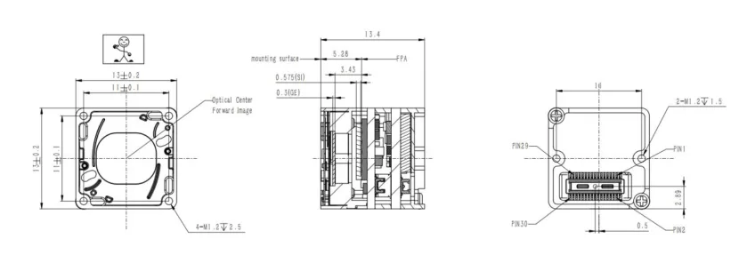
In multi-rotor and fixed-wing gimbals, mechanical balance is critical. AeroMini 640 specifies <20 g and 21 × 21 × 28 mm, excluding lens and flange. SuperMini 640 / 640T specify a <3.5 g, 13 × 13 × 13.4 mm bare core, excluding optics and boards. Neither figure is a complete airborne payload specification. Include the chosen lens, interface board, cables, enclosure, and mounting hardware in the mass and center-of-gravity budget before selecting gimbal motors.
Power Dissipation and Thermal Management
Microbolometers detect small temperature differences, so internal heat build-up can cause thermal drift. AeroMini 640 specifies <0.5 W typical module consumption at 25°C; allow separately for interface hardware, regulators, processing, and other payload loads. In sealed airborne pods, design a suitable conduction path, such as thermal gap pads between an approved mounting surface and an aluminum enclosure. Validate temperatures and image stability under the actual sun exposure, airflow, and duty cycle rather than assuming that low typical consumption guarantees passive cooling.
Shock and Vibration Resilience
UAV airframes subject payloads to motor vibration and shock during takeoff or landing. Request the qualification limits and test conditions for the exact camera, lens, interface board, and mounting arrangement. Check connector retention, cable strain relief, image stability, and focus before and after representative vibration tests. Do not transfer an older module’s shock or vibration rating to AeroMini 640 or SuperMini 640 / 640T.
3. Video Transmission & Protocol Architecture: Analog CVBS vs. Digital USB/MIPI vs. SPI
Your hardware interface determines video latency, CPU overhead on companion computers, and down-link bandwidth efficiency across your datalink.
Analog CVBS (Composite Video Baseband Signal)
For First-Person View (FPV) observation and situational awareness, analog CVBS remains a practical video path. Routing baseband video into a compatible analog transmitter can avoid some digital encoding stages, but it does not guarantee zero or sub-10 ms glass-to-glass latency. Detector timing, camera processing, transmitter, receiver, and display all contribute; measure the complete selected chain before relying on it in flight. For a detailed breakdown of analog transmission architectures, review our engineering guide on CVBS thermal camera module analog video integration.
Digital USB & MIPI
When integrating thermal payloads with onboard companion edge-AI computing platforms (such as NVIDIA Jetson Orin, Raspberry Pi CM4, or Qualcomm Flight architectures), digital data pipelines are essential:
- ✅ USB (UVC – USB Video Class): A supported UVC configuration can simplify image-stream access, but UVC enumeration does not prove radiometric output, RAW bit depth, or ROS compatibility. Confirm the selected camera version, board, firmware, pixel format, frame rate, and host software. Temperature data requires an explicitly supported radiometric configuration and documented decoding path.
- ⚙️ MIPI: A compact digital link for supported embedded hosts. Match lane count, electrical levels, clocking, transport protocol, pixel format, and the host driver before designing the carrier board; a MIPI label alone does not establish CSI-2 or ISP compatibility. AeroMini and SuperMini connector definitions are different and are not interchangeable.
SPI (Serial Peripheral Interface)
Some small thermal modules use SPI for control or image transfer. Check the actual device protocol, transfer bandwidth, and frame timing: SPI support and power consumption are module-specific. The AeroMini 640 and SuperMini 640 / 640T paths compared below should be designed from their own published interfaces, not from an unrelated SPI module’s wiring or power figures.
Command and Control: RS-422 and USB Serial
Controlling a thermal module during flight, such as selecting palettes or requesting a supported correction cycle, requires a matched command protocol and electrical interface. AeroMini lists UART, RS232, and RS422 as board-dependent options; SuperMini’s bare-core UART uses 1.8 V logic. Differential RS422 can improve noise tolerance when correctly implemented, but it does not by itself provide galvanic isolation or aviation certification. Confirm logic levels, grounding, transceivers, and the available commands for the supplied board.
4. Core Comparison: Sourcing Uncooled LWIR Modules for Drone Payloads
Choose a core by the required imaging or thermography workflow, target GSD, complete payload mass, and host integration effort. AeroMini 640 is the primary UAV module considered here; SuperMini 640 / 640T provide a smaller bare-core alternative with a different connector and power architecture. Explore the broader drone camera integration ecosystem, and confirm the ordered configuration against its current documentation.
AeroMini 640 640×512 UAV Thermal Imaging Module
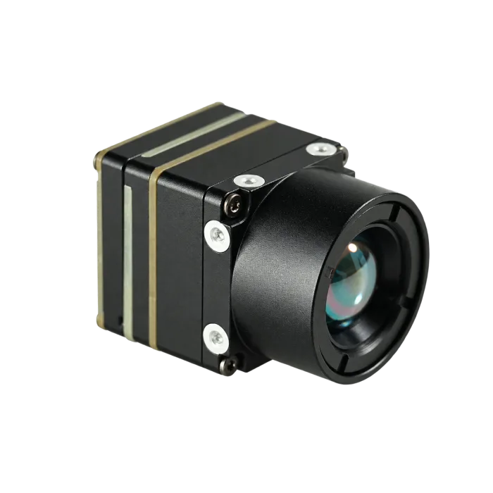
The AeroMini 640 combines a 640 × 512, 12 μm VOx detector with a choice of interface packages. Start by separating non-radiometric viewing from radiometric measurement: the current non-radiometric configuration defaults to 60 Hz, while the 25 Hz radiometric version is an availability enquiry.
- ✅ Imaging Configuration: 60 Hz default, with a 30 Hz factory option selected when ordering.
- ⚙️ Radiometric Enquiry: 25 Hz; documented 9, 13, and 18 mm lenses. Confirm availability, output format, and measurement requirements.
- ✅ Published SWaP: <20 g and 21 × 21 × 28 mm, excluding lens and flange; <0.5 W typical module power at 25°C.
- ⚙️ Board Selection: USB + CVBS + MIPI and Type-C + CVBS are separate tailboard configurations. Match the ordered board, cable, and firmware.
| AeroMini 640 Technical Specifications | |
|---|---|
| Detector & Pixel Pitch | 640 × 512 uncooled VOx / 12 μm / 8–14 μm LWIR |
| Non-radiometric Frame Rate | 60 Hz default; 30 Hz factory option, selected when ordering |
| Radiometric Version | 25 Hz; availability enquiry only. Documented radiometric lenses: 9 / 13 / 18 mm; confirm interface, accuracy, and data format |
| NETD | ≤30 mK at 25°C, F/1.0; this is sensitivity, not temperature accuracy |
| Dimensions & Weight | 21 × 21 × 28 mm / <20 g, excluding lens and flange |
| Power | <0.5 W typical at 25°C; complete-kit consumption may differ |
| Supply & Interface Boards | Board-dependent supply. The illustrated 16-pin POWER_IN1 and 26-pin POWER_IN2 inputs are 5 V only, not 12 V. Type-C + CVBS is a separate board |
| Operating Temperature | −40°C to +80°C; validate the complete payload and optics separately |
SuperMini 640 / 640T Ultra-Light LWIR Thermal Camera Module
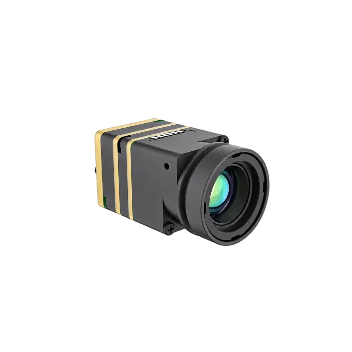
The SuperMini 640 / 640T family offers a smaller bare-core reference for payloads where the host carrier and optical assembly can be engineered around its 30-pin interface. Both models use a 640 × 512, 8 μm array, but their imaging and thermography modes must not be interchanged.
- ✅ SuperMini 640: Imaging model at 50 Hz.
- ⚙️ SuperMini 640T: Thermographic model at 30 Hz; confirm the supported temperature-data path for your host.
- ✅ Bare-Core Reference: <3.5 g and 13 × 13 × 13.4 mm, excluding optics and boards.
- ⚙️ Integration Scope: Add optics, carrier or expansion board, regulators, cables, and enclosure to establish actual assembly weight, dimensions, and power.
| SuperMini 640 / 640T Integration Specifications | |
|---|---|
| Resolution & Pixel Pitch | 640 × 512 / 8 μm |
| Model & Frame Rate | SuperMini 640: imaging, 50 Hz. SuperMini 640T: thermography, 30 Hz |
| Bare-Core Dimensions & Weight | 13 × 13 × 13.4 mm / <3.5 g, excluding optics and boards |
| Lens Options | 3.7 / 6.1 / 8.7 / 11 mm; confirm the assembly drawing for the selected lens and board |
| Core Power Rails | MAIN_POWER 3.8–5.2 V (typical 5 V), +3.3 V rail 3.28–3.32 V, and +1.8 V rail 1.78–1.82 V; follow the manual’s current and noise limits |
| Digital Paths | 8-bit LVCMOS and 2-lane MIPI; model-specific BT656 (640) / CDS3 (640T). BT656 and MIPI cannot operate simultaneously |
| Control & Analog Output | UART uses 1.8 V logic, TX/RX referenced to the core. The core CVBS output requires an external video-buffer IC |
| Connector Scope | 30-pin core interface without an expansion board; do not use AeroMini 16/26-pin definitions or infer a USB-C kit pinout |
Side-by-Side Payload Sourcing Matrix
| Parameter | AeroMini 640 | SuperMini 640 | SuperMini 640T |
|---|---|---|---|
| Selection Focus | UAV imaging with a selected tailboard; radiometric version by enquiry | Compact bare-core imaging integration | Compact bare-core thermography integration |
| Detector Array / Pitch | 640 × 512 / 12 μm | 640 × 512 / 8 μm | 640 × 512 / 8 μm |
| Frame Rate | Non-radiometric: 60 Hz default / 30 Hz factory option; radiometric: 25 Hz enquiry | 50 Hz imaging | 30 Hz thermography |
| Mechanical Reference | <20 g; 21 × 21 × 28 mm; excludes lens and flange | <3.5 g; 13 × 13 × 13.4 mm; excludes optics and boards | Same bare-core reference; excludes optics and boards |
| Power Budget | <0.5 W typical module power at 25°C; budget complete kit separately | Use all required rails and the selected board’s budget; no complete-kit wattage inferred | Use all required rails and the selected board’s budget; no complete-kit wattage inferred |
| Interface Boundary | USB/CVBS/MIPI board has illustrated 16/26-pin references; Type-C board is separate | 30-pin core; 1.8 V UART; model-specific video paths | 30-pin core; 1.8 V UART; CDS3 temperature-data path documented |
| Radiometry Check | 25 Hz version only; confirm accuracy, RAW/data format, and interface | Imaging model; do not assume temperature output | Thermographic model; confirm host decoding and calibration requirements |
5. Critical Optical & Environmental Design Considerations
Taking thermal cameras into the air exposes them to optical and physical conditions that bench testing never fully replicates. Flight speed, rotor downwash, rapid climbs, and sub-zero atmospheric temperatures require thoughtful optomechanical engineering.
Infrared Lens Materials and Protective Coatings
Standard optical glass (like fused silica or BK7) is completely opaque to infrared radiation in the 8 to 14 μm waveband. UAV thermal lenses demand dedicated materials:
- ⚙️ Monocrystalline Germanium (Ge): Germanium boasts a high refractive index (~4.0) and minimal optical dispersion across the LWIR spectrum, allowing for compact, fast (low F-number) optical designs. Select a durable protective coating for the expected environment; Diamond-Like Carbon (DLC) is one option. Confirm optical transmission, abrasion resistance, and the exact lens assembly’s environmental test results. A coating label alone does not guarantee protection against rain erosion or salt fog.
- ⚙️ Chalcogenide Glass: Chalcogenide compounds can be precision-molded into intricate aspheric and diffractive profiles. This allows optical engineers to create lightweight, multi-element lens assemblies using fewer individual pieces, shaving critical grams off the gimbal assembly.
Athermalized Optical Assemblies
Temperature changes can shift focus through lens and barrel expansion. Evaluate athermalized optics or another validated focus strategy for the actual flight envelope; a camera’s electronics temperature rating is not a guarantee of lens focus stability. AeroMini 640 publishes an operating range of −40°C to +80°C. Confirm the selected lens assembly’s performance across that range and test it in the final enclosure.
Non-Uniformity Correction (NUC) and Shutter Strategies
Every individual microbolometer pixel has slight gain and offset variances that shift as the camera’s internal temperature changes. Keeping imagery crisp and radiometrically uniform requires routine Non-Uniformity Correction (NUC):
- ⚙️ Mechanical Shutter NUC: Where fitted, a shutter presents a uniform reference for correction. Duration and triggering are configuration-specific; measure any image interruption and design the payload software to flag affected frames. Do not rely on uninterrupted thermal imagery for flight control.
- ⚙️ Scene-Based Shutterless Correction: Some modules use scene information to reduce fixed-pattern artifacts without a mechanical shutter cycle. Confirm whether the selected firmware supports this approach and test its behavior with low-contrast or stationary scenes; it is not a blanket guarantee of uninterrupted, artifact-free tracking.
6. Step-by-Step OEM Payload Integration & Prototyping Roadmap
Taking an uncooled LWIR core from benchtop prototyping to fully qualified airborne flight requires a disciplined, step-by-step systems engineering workflow.
-
⚙️ Phase 1: Lab Bench Bring-Up and SDK Evaluation
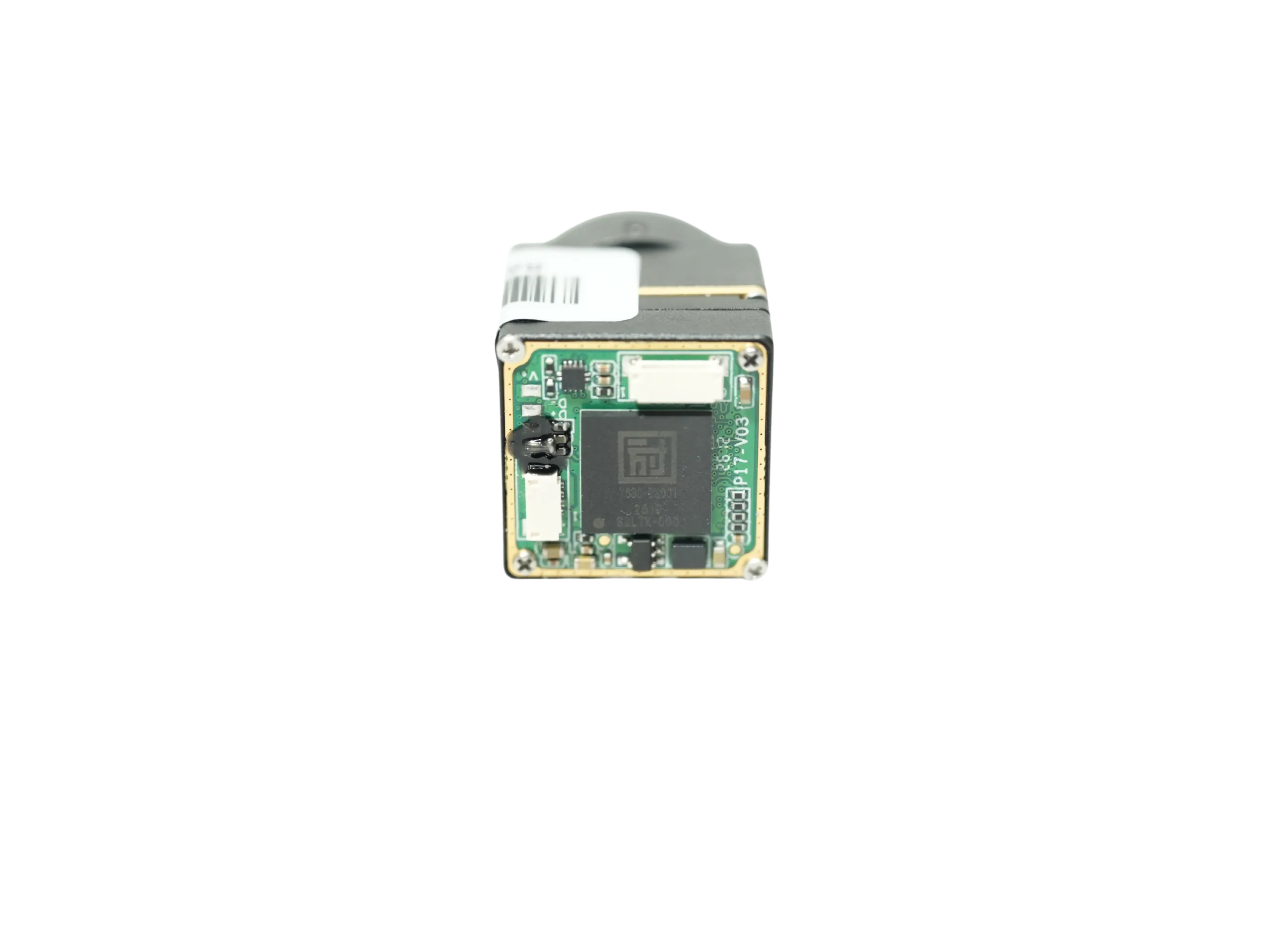
Start with the exact ordered camera, interface board, cable, and firmware. For AeroMini 640, verify host enumeration where UVC is supported, the negotiated image format and frame rate, and the documented control commands. Its official SDK FAQ points to a public resource folder containing manuals, USB Client Software.zip, and USB-SDK.zip; the FAQ describes the SDK archive as Linux drivers, examples, and SDK resources. These links are documentation references, not a tested compatibility claim. For SuperMini 640 / 640T, use its own Product Manual V1.0.0 and confirm model-specific host software; do not reuse the AeroMini SDK by assumption. Review sample procurement and return policies when ordering evaluation units. -
⚙️ Phase 2: Power Rail Conditioning and EMI Shielding
Keep camera supplies within the exact board’s limits and check startup current, ripple, grounding, and signal integrity with the motors and radios running. Do not connect an unregulated flight battery directly to a module. AeroMini’s illustrated POWER_IN1 / POWER_IN2 pins accept 5 V only; a board-family listing of 5 V or 12 V does not authorize 12 V on those pins. SuperMini’s bare core requires its documented MAIN_POWER, +3.3 V, and +1.8 V rails, with UART at 1.8 V logic. Choose filtering, regulators, shielding, and cable routing from the measured noise environment and the matched manual, rather than applying one generic regulator or wiring recipe to every board. -
⚙️ Phase 3: Gimbal Mechanical Integration and Balancing
Secure the camera according to its mounting guidance inside a suitable protective housing. Balance the complete payload, including lens, boards, cables, and enclosure, about the intended gimbal axes. Proper static balance can reduce steady-state motor load; verify clearance, cable forces, dynamic stability, and motor temperatures in the final assembly. -
⚙️ Phase 4: Telemetry Synchronization & Autopilot Integration
Implement a host-side bridge between documented camera commands and the required autopilot messages (such as MAVLink on PX4 or ArduPilot); do not assume native camera support. Timestamp frames alongside position, height above the target, and gimbal orientation, then measure synchronization error. Radiometric mapping additionally requires a supported radiometric model, calibrated temperature data, and a validated processing workflow.
AeroMini Board, Cable, and PIN References
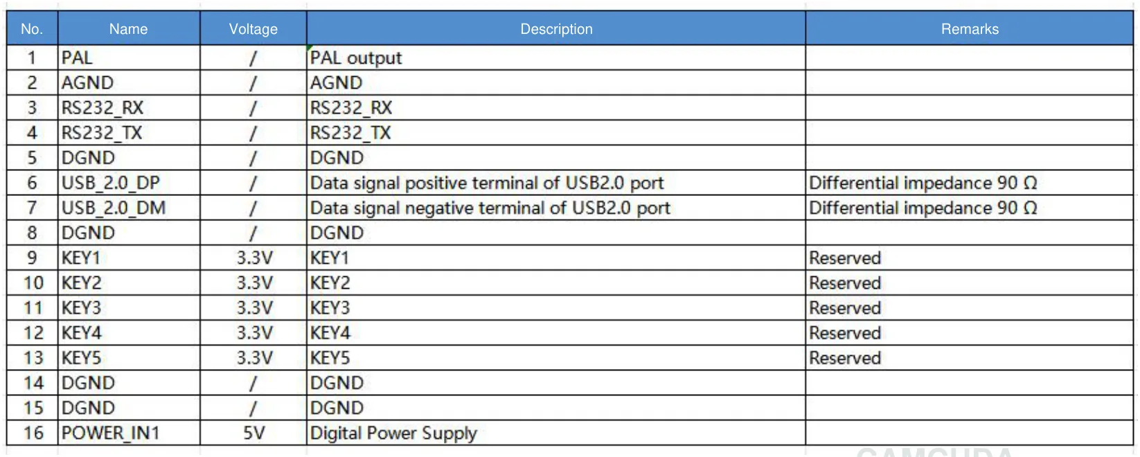
The following two figures refer to the USB + CVBS + MIPI tailboard configuration. The Type-C + CVBS board is separate: do not apply the 16-pin or 26-pin definitions to its connectors, and do not infer a Type-C pinout from cable colors.
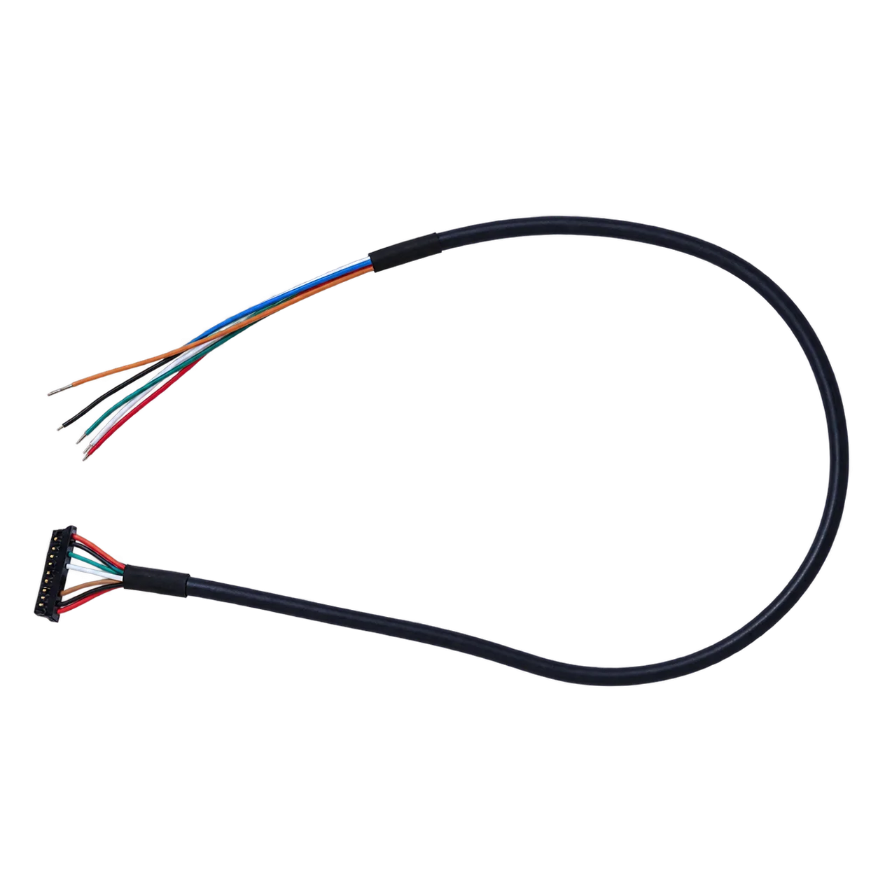

Use the schematic with the complete 16-pin signal table and the official AeroMini PDF (page 3). The table identifies pin 1 as PAL, pin 6 as USB_2.0_DP, pin 7 as USB_2.0_DM, and pin 16 as POWER_IN1 (5 V). Confirm the matched board layout and mating orientation before wiring. The separate 26-pin MIPI/DVP reference is on page 4; its POWER_IN2 pins are also 5 V inputs. Do not apply 12 V to POWER_IN1 or POWER_IN2.
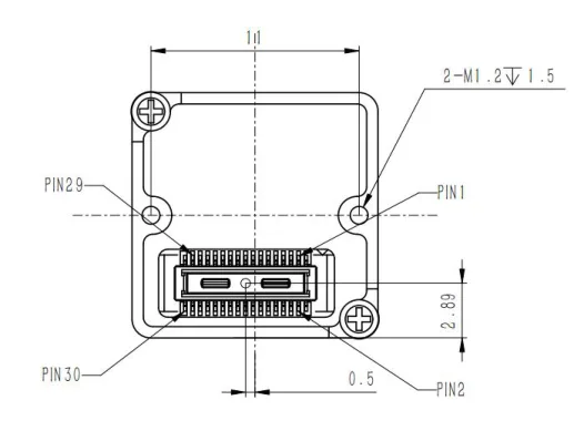
SuperMini 640 / 640T use a different 30-pin core orientation drawing. Read it with the full signal table on PDF pages 6–7 of the SuperMini manual; those definitions apply to the core without an expansion board, not to an AeroMini or Type-C connector. For packaging, the bare-core mechanical drawing excludes the lens and expansion board, so obtain the correct assembled drawing before finalizing a gimbal enclosure.
7. Commercial & Industrial Application Blueprints
Deploying thermal imaging drones across industrial environments addresses mission-critical challenges across multiple commercial verticals.
1. Utility-Scale Photovoltaic (PV) Solar Plant Auditing
Solar-farm inspection planning must match target defect size, lens, GSD, flight speed, and thermal conditions. AeroMini 640 offers a 640×512, 12 μm array and ≤30 mK NETD at 25°C, F/1.0 for image capture, but these specifications do not guarantee detection or eliminate reflection-related false positives. For temperature measurements, enquire about its 25 Hz radiometric version or evaluate SuperMini 640T at 30 Hz, with the required data output and calibration confirmed before deployment.
2. High-Voltage Transmission Line and Substation Monitoring
Corroded splices, failing transformer bushings, and phase imbalances can produce thermal anomalies. Select frame rate and flight speed together: AeroMini 640 non-radiometric imaging defaults to 60 Hz (30 Hz factory option), SuperMini 640 imaging is 50 Hz, and thermographic versions have their own rates. Higher frame rate alone does not eliminate blur. Validate the complete camera-control and video chain in the expected electromagnetic environment; differential serial signaling is not galvanic isolation.
3. Search and Rescue (SAR) & Wildfire Management
For search and rescue across open terrain, thermal contrast can help reveal a person when there is a usable line of sight. LWIR cannot see through dense foliage or solid cover; canopy gaps, viewing angle, weather, and target exposure determine visibility. During wildfire response, thermal imaging can sometimes improve visibility through smoke and help assess surface hotspots, but smoke conditions and intervening materials still limit the view. It does not directly reveal underground fires through soil.
4. Confined-Space and Indoor Building Diagnostics
Confined-space inspection places a premium on total assembled mass, close-focus performance, heat management, and safe navigation. SuperMini 640 / 640T offer a <3.5 g bare-core reference, excluding optics and boards, but lens, carrier, power conversion, cabling, and protection can materially change the payload budget. Choose the 50 Hz imaging or 30 Hz thermographic model for the actual inspection task and verify minimum focus distance and complete-system power; do not rely on thermal imagery alone for obstacle avoidance.
8. Comprehensive Drone Thermal Payload Engineering FAQ
Why are turnkey enterprise thermal drones so expensive, and how do OEM cores provide a cost-effective alternative?
What video interface and frame rate parameters are essential for UAV thermal integration?
How should I choose between AeroMini 640 and SuperMini 640 / 640T for a UAV payload?
Choose AeroMini 640 when its UAV-oriented interface packages, 12 μm array, and 60 Hz default non-radiometric imaging fit the host and payload budget; select the 30 Hz factory option when required, or enquire separately about 25 Hz radiometry. Choose SuperMini 640 / 640T when an 8 μm, smaller bare core suits a custom carrier and optical design: 640 is 50 Hz imaging, and 640T is 30 Hz thermography. Both families are 640×512, so compare lens FOV, GSD, required temperature output, complete assembled mass/power, and integration effort rather than resolution alone. Their connector and power definitions are different and cannot be transferred between families.
📚 References & Further Reading
- Aviation Background: ICAO Unmanned Aviation
- Scientific Principles: Wikipedia – Thermography
- Related Guide: CVBS Thermal Camera Module Analog Video Integration
- Product Ecosystem: Modular Drone Camera Integration Solutions
- AeroMini Documentation: Current product specifications, official PDF, and SDK FAQ
- SuperMini Documentation: Current 640 / 640T specifications and Product Manual V1.0.0
- Optical Planning: Thermal Imaging Calculator
- Procurement Policy: CamCuda Evaluation & Refund Policy