Thermal Image Drone Payloads: OEM 640 LWIR Modules & Selection Guide
Thermal Image Drone Payloads: OEM 640 LWIR Modules & System Architecture Selection Guide
Uncooled long-wave infrared (LWIR) camera payloads have evolved from high-cost, specialized aerospace instruments into mission-critical modular subsystems across commercial, industrial, public safety, and tactical unmanned aerial systems (UAS). Building an agile, mission-effective thermal image drone requires optical, avionics, and mechanical systems engineers to navigate real-world SWaP-C (Size, Weight, Power, and Cost) trade-offs. The modern OEM sensor market has shifted away from heavy, power-hungry legacy thermal assemblies toward sub-3.5g micro-cores and ruggedized wide-voltage analog units. These compact form factors allow system architects to deploy high-resolution 640×512 Vanadium Oxide (VOx) focal plane arrays across lightweight multi-rotors, continuous-operation tethered inspection platforms, micro-gimbals, fixed-wing scouting drones, and first-person view (FPV) airframes.
Here’s the deal: picking the right thermal payload involves far more than comparing raw pixel counts on a spec sheet. In the shop, integrators have to balance thermal sensitivity (NETD ≤40 mK), pixel pitch architecture (from standard 12 μm nodes down to modern 8 μm arrays), athermalized optical fields of view, and video interfaces ranging from zero-latency analog CVBS (PAL/NTSC) to high-throughput 2-lane MIPI CSI-2 and 8-bit BT.656 digital streaming buses. On top of that, deciding whether a flight profile demands high-contrast spatial imaging (50 Hz/60 Hz) or calibrated radiometric surface temperature data (like the CDS3 protocol on the SuperMini 640T) dictates the entire mechanical envelope, avionics bus, and edge-processing pipeline.
Look at the engineering reality: if your thermal core pulls too much power or dumps heat directly into sensitive avionics, your flight times drop and your image degrades fast. This engineering guide digs into the mechanics, optics, signal transport, and integration protocols required to build and optimize field-ready OEM 640 thermal drone payloads that perform under real flight conditions.
Table of Contents
- 👉 1. Thermal Drone Payload Fundamentals: Uncooled VOx Physics & SWaP Optimization
- 👉 2. Sensor Architectures, Pixel Pitch & Athermalized Optics Selection
- 👉 3. Video Pipelines, Interface Protocols & Edge Compute Integration
- 👉 4. OEM 640 LWIR Product Showcase & Comparative Specifications
- 👉 5. Step-by-Step Engineering Selection Framework for Drone Payloads
- 👉 6. Mechanical, Thermal, and Power Integration Best Practices
- 👉 7. Deep-Dive Frequently Asked Questions (FAQ)
1. Thermal Drone Payload Fundamentals: Uncooled VOx Physics & SWaP Optimization
Integrating infrared sensing into unmanned aerial systems begins at the microbolometer focal plane array (FPA). Most modern thermal drone payloads operate right in the long-wave infrared (LWIR) atmospheric transmission window between 8 and 14 μm. Unlike cooled thermal imaging sensors—which rely on semiconductor photon detectors like Indium Antimonide or Mercury Cadmium Telluride mated to cryogenic Stirling coolers running at ~77 K—commercial and tactical drone systems rely almost exclusively on uncooled Vanadium Oxide (VOx) microbolometers.
A VOx microbolometer array consists of microscopic silicon-machined bridge structures suspended over a readout integrated circuit (ROIC) by thermally resistive legs inside a vacuum-sealed package. When incident LWIR radiation focuses through the optical assembly onto the active pixel area, the VOx thin film absorbs that infrared energy, raising its temperature. This change in temperature induces a measurable shift in electrical resistance through its Temperature Coefficient of Resistance (TCR, typically −2% to −3% per Kelvin). The underlying ROIC samples these resistance shifts line by line, converting analog voltage variances into raw digital counts for downstream processing.
VOx microbolometers deliver solid advantages over alternative materials like Amorphous Silicon (α-Si):
- ✅ Higher Thermal Conductivity: Absorbs and dissipates energy rapidly without thermal lag.
- ✅ Superior TCR Stability: Provides consistent temperature-to-resistance response curves across operating ambient swings.
- ✅ Lower 1/f Flicker Noise: Yields cleaner low-frequency signal transitions and sharper image contrast.
- ✅ Fast Thermal Time Constants (τ ~ 8–12 ms): Prevents ghosting and smear during dynamic roll, pitch, and yaw maneuvers.
Thermal Sensitivity (NETD) and Signal-to-Noise Dynamics
The baseline benchmark for thermal sensor performance in aerial environments is Noise Equivalent Temperature Difference (NETD), measured in millikelvins (mK). NETD represents the temperature difference on a blackbody target that produces a signal-to-noise ratio (SNR) of exactly one at the detector output. Mathematically, NETD is governed by detector area, optics speed, and radiative physics:
NETD ∝ [ 4 × (F/#)² ] / [ π × Ad × τoptics × (Δλ) × (∂L / ∂T) ]
Where F/# is the optical f-number (aperture ratio), Ad is the detector pixel area, τoptics is optical transmission efficiency, Δλ is spectral bandwidth (8–14 μm), and ∂L/∂T is the rate of change of blackbody radiance with respect to temperature. In aerial work where targets show minimal contrast against background clutter (think maritime search and rescue, dense tree canopy operations, or overcast farmland), a sensor core with an NETD ≤40 mK at 25°C, F1.0 is essential. This sensitivity allows edge-detection algorithms and human operators to pull targets out of background clutter cleanly.
The SWaP-C Optimization Challenge in UAV Engineering
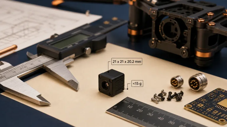
Every single gram on an airframe counts against flight endurance, climb rate, motor thermals, and battery sizing. On standard multi-rotors, adding just 20 grams of payload mass can chop 1.5 to 3 minutes off your hover time depending on disc loading. Historically, 640×512 thermal cores weighed between 60g and 120g bare, demanding bulky mechanical gimbals just to keep them steady. Today, advancements in sub-micron semiconductor lithography have delivered cores like the CAMCUDA SuperMini 640, which packs a full 640×512 VOx sensor into a 13 × 13 × 13.4 mm core weighing less than 3.5 grams while drawing ≤0.5 W. That compact footprint makes dual-sensor EO/IR 3-axis stabilized micro-gimbals weighing under 60 grams total an everyday reality.
2. Sensor Architectures, Pixel Pitch & Athermalized Optics Selection
Pixel pitch—the center-to-center spacing between neighboring sensor pixels—is the starting point for aerial optomechanics. The market has moved from 17 μm down to 12 μm, and now to ultra-dense 8 μm pixel pitch arrays. That shift completely changes optical sizing for drone builders.
The Impact of 8 μm Pixel Pitch on Gimbal Payloads
Dropping pixel pitch from 12 μm to 8 μm shrinks the active surface area of a 640×512 focal plane array from 7.68 × 6.14 mm (diagonal ~9.83 mm) down to 5.12 × 4.09 mm (diagonal ~6.55 mm). That 55% reduction in focal plane footprint delivers major engineering advantages:
- ✅ Optics Miniaturization: To match an equivalent Field of View (FOV), an 8 μm sensor needs a much shorter focal length than a 12 μm sensor. A 6.1 mm lens on an 8 μm core gives you a 46.6° × 37.6° FOV, whereas a 12 μm sensor needs a 9.0 mm lens to achieve a similar 46.2° × 37.7° FOV. Shorter focal lengths mean smaller lens diameters and thinner, lighter Germanium or Chalcogenide elements.
- ✅ Gimbal Torque & Inertia Reduction: In motorized 2-axis and 3-axis gimbals, mechanical inertia follows the mass times the square of the distance from the pivot (I = m × r²). Smaller optical assemblies pull center-of-gravity inward toward pitch and yaw axes, cutting continuous motor torque demand and eliminating stabilization oscillations during aggressive flight.
Instantaneous Field of View (IFOV) and Drift Prevention
Spatial resolution in aerial thermal imaging is defined by Instantaneous Field of View (IFOV), measuring the angular coverage of an individual pixel. Calculate IFOV directly from pixel pitch (p) and lens focal length (f):
IFOV (mrad) = [ Pixel Pitch (μm) / Focal Length (mm) ]
A smaller IFOV gives you finer spatial detail and longer detection ranges, but narrows your overall field of view. The table below breaks down the optical trade-offs across common athermal lens assemblies:
| Lens Focal Length | Pixel Architecture | Field of View (H × V) | IFOV | Aperture | Primary UAS Flight Application |
|---|---|---|---|---|---|
| 3.7 mm | 8 μm (SuperMini) | 90.0° × 68.2° | 2.16 mrad | F1.0 | Close-proximity obstacle avoidance, indoor navigation, wide situational awareness |
| 6.1 mm | 8 μm (SuperMini) | 46.6° × 37.6° | 1.31 mrad | F1.0 | General aerial patrol, Search & Rescue (SAR), agricultural mapping |
| 8.7 mm | 8 μm (SuperMini) | 40.0° × 32.2° | 0.92 mrad | F1.0 | Powerline & solar farm inspection, structural defect analysis |
| 11.0 mm | 8 μm (SuperMini) | 24.9° × 20.0° | 0.73 mrad | F1.0 | High-altitude perimeter surveillance, tactical reconnaissance |
| 9.0 mm | 12 μm (W640-TIF-K1) | 46.2° × 37.7° | 1.33 mrad | F1.0 | Tactical FPV scouting, analog video downlink integration |
Athermal Optical Barrel Design
Drones hit drastic ambient temperature changes when climbing through atmospheric inversion layers or running through extreme weather (−20°C to +60°C). Standard infrared glass elements have high thermo-optic coefficients (dn/dT), meaning optical focus will drift rapidly without mechanical compensation. Aerial thermal payloads require athermalized F1.0 optical assemblies. These setups pair optical elements like Chalcogenide glass and Germanium with mechanical housing materials (such as aluminum and Delrin) whose thermal expansion cancels out refractive shifts. This passive approach keeps your imagery sharp across the whole operating envelope without adding the weight, power, or complexity of motorized focus units.
When engineering multi-sensor gimbal payloads that combine long-range observation and target rangefinding, systems engineers frequently pair these uncooled LWIR cores with visible modules like the ERA-X Series Visible Light Rangefinder Payload, or step up to megapixel-class arrays like the HR 1280 Megapixel Uncooled LWIR Core.
3. Video Pipelines, Interface Protocols & Edge Compute Integration
Hooking an OEM thermal module into an airframe requires matching the sensor’s physical and electrical interface to your flight avionics, companion processor, and wireless downlinks. Modern UAS builds generally fall into two integration paths: zero-latency analog setups or high-throughput digital edge-compute pipelines.
Analog CVBS Architecture for Tactical & FPV Systems
For high-speed FPV tactical drones, fast-response scouting airframes, and quick retrofit projects, direct Composite Video Baseband Signal (CVBS) output remains a dependable workhorse. Modules like the W640-TIF-K1 CVBS Module output standard analog PAL/NTSC video over a compact 3-pin SMD connector (Pin 1: CVBS Video, Pin 2: Ground, Pin 3: DC Power 5–18V). This architecture brings distinct perks to the flight line:
- ✅ Near-Zero Latency: The raw analog feed ties directly into 5.8 GHz or 1.3 GHz analog video transmitters (VTx), bypassing digital compression buffers. You get end-to-end glass-to-glass latency under 5 milliseconds for pinpoint manual stick control.
- ✅ Wide Voltage Tolerance: With an onboard 5–18V DC input regulator, you can tap straight into 2S, 3S, or 4S flight battery packs without noisy intermediate buck converters.
- ✅ Zero Software Overhead: No companion OS, no Linux kernel drivers, and no frame-grabber boards required. For complete wiring and pinout details, refer to the in-depth guide on CVBS Thermal Camera Module Analog Video Integration.
Digital Buses (MIPI CSI-2, 8-Bit BT.656) for Edge-AI & Companion Compute
When your mission demands autonomous obstacle avoidance, automated object tracking, sensor fusion, or real-time temperature telemetry, the thermal core must tie directly into an onboard companion computer like an NVIDIA Jetson Orin Nano, Raspberry Pi CM4, or dedicated NPU. The CAMCUDA SuperMini 640 line exposes digital streaming over a 30-pin Hirose DF40C-30DP-0.4V(51) board-to-board connector:
- ⚙️ 2-Lane MIPI CSI-2: Feeds uncompressed digital thermal frames straight into the host processor’s hardware Image Signal Processor (ISP) with minimal CPU loading. This interface delivers the raw throughput needed for edge AI models running YOLOv8 detection or automated perimeter sweeps.
- ⚙️ 8-Bit LVCMOS / BT.656: Delivers clocked parallel digital video for microcontrollers, FPGAs, and onboard hardware video encoders. On the SuperMini 640, this bus delivers BT.656 digital video; on the SuperMini 640T, it streams full CDS3 radiometric telemetry frames.
- ⚙️ 1.8V UART Command Bus: Allows the flight controller or companion computer to adjust digital zoom, switch color palettes (White Hot, Black Hot, Rainbow, Ironbow), trigger non-uniformity correction (NUC) shutter events, and adjust region-of-interest (ROI) AGC profiles on the fly.
Thermal Imaging vs. Radiometric Telemetry
Look, before cutting metal or ordering boards, you must choose between spatial imaging cores and calibrated radiometric thermography cores:
- 📌 Spatial Thermal Imaging (e.g., SuperMini 640 & W640-TIF-K1): Configured to output clean 8-bit dynamic contrast video. The internal ISP applies histogram equalization, automatic gain control (AGC), and digital detail enhancement (DDE) to pull out edges, human silhouettes, vehicles, and structures. Frame rates run at 50 Hz or 60 Hz for fluid motion. Pixel values represent relative thermal contrast, not absolute degrees.
- 📌 Radiometric Thermography (e.g., SuperMini 640T): Undergoes multi-point factory blackbody calibration across its full operating envelope (−20°C to +150°C and 100°C to +650°C). Running at a steady 30 Hz frame rate, every pixel in the 640×512 array represents an absolute temperature value transmitted over CDS3 or MIPI metadata streams. This is the hardware you need for utility transformer diagnostics, solar panel cell defect analysis, and industrial flare-stack monitoring. These data pipelines easily tie into open-source ecosystems like PX4 Autopilot or specialized radiometric processing platforms like Workswell.
4. OEM 640 LWIR Product Showcase & Comparative Specifications
Selecting the right OEM thermal sensor requires matching the core’s electrical, optical, and mechanical specifications to your drone’s payload constraints. Below is a comprehensive engineering breakdown of CAMCUDA’s field-proven 640 LWIR camera modules.
CAMCUDA SuperMini 640 / 640T Ultra-Light LWIR Thermal Camera Module
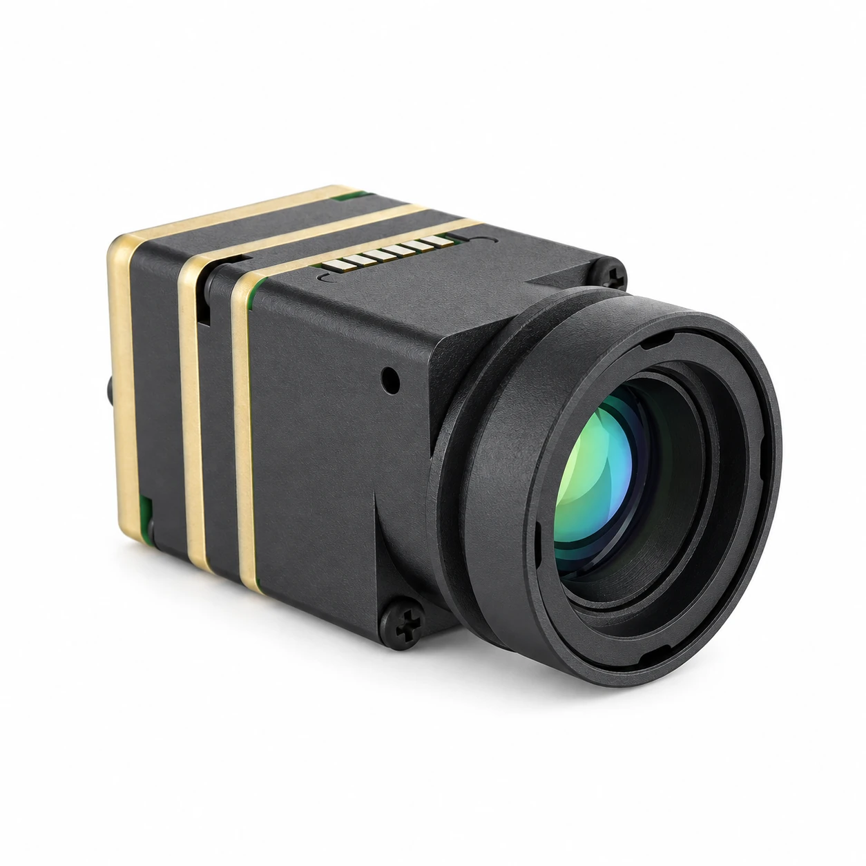
The CAMCUDA SuperMini 640 / 640T is an ultra-miniature LWIR thermal camera core built for tight SWaP-constrained drone integrations, micro-gimbals, and embedded UAV avionics. Powered by an uncooled 640×512 VOx focal plane array on an 8 μm pixel pitch, the bare core measures just 13 × 13 × 13.4 mm and weighs under 3.5 grams. Drawing ≤0.5 W, the series comes in two factory versions: the 50 Hz SuperMini 640 for dynamic spatial imaging and the 30 Hz SuperMini 640T for radiometric thermography.
| Detector & Optomechanics | |
|---|---|
| Detector Type | Uncooled Vanadium Oxide (VOx) Focal Plane Array |
| Resolution | 640 × 512 active pixels |
| Pixel Pitch | 8 μm |
| Spectral Range | 8–14 μm (LWIR) |
| Thermal Sensitivity (NETD) | ≤40 mK @ 25°C, F1.0 |
| Frame Rates | SuperMini 640: 50 Hz | SuperMini 640T: 30 Hz |
| Athermal Lens Options | 3.7 mm (90.0°×68.2°) | 6.1 mm (46.6°×37.6°) | 8.7 mm (40.0°×32.2°) | 11 mm (24.9°×20.0°) |
| Electrical, Interface & Radiometry | |
| Radiometric Range (640T Only) | −20°C to +150°C (Low Range) | 100°C to +650°C (High Range) |
| Board Interface Connector | Hirose DF40C-30DP-0.4V(51) 30-Pin Receptacle |
| Digital Video Buses | 2-Lane MIPI CSI-2 | 8-Bit LVCMOS (640: BT.656 / 640T: CDS3) |
| Command & Control Interface | UART (1.8V Logic Levels, TX/RX) |
| Operating Voltage Requirements | MAIN: 3.8–5.2 V (Typ 5V, ≤10mV p-p noise) | +3.3V (3.28–3.32V) | +1.8V (1.78–1.82V, ≤1mV RMS) |
| Typical Core Power Draw | ≤0.5 W |
| Core Dimensions & Weight | 13 × 13 × 13.4 mm | < 3.5 g (Excluding lens and interface board) |
View Product Details & Pricing ➔
CAMCUDA W640-TIF-K1 640×512 CVBS Analog Thermal Imaging Module

The CAMCUDA W640-TIF-K1 is an integrated analog thermal imaging module built for tactical FPV platforms, small unmanned aircraft, and direct analog camera replacements. Designed around a 12 μm 640×512 VOx sensor with a factory-installed 9.0 mm athermal lens (46.2° × 37.7° FOV), it outputs clean CVBS (PAL) video over a 3-pin SMD connector. With a wide 5–18V DC input tolerance, low power draw of ≤0.8W, and an enclosed ruggedized chassis weighing 56.5g, it delivers plug-and-play analog thermal capability without requiring companion boards.
| Technical Parameters for OEM Evaluation | |
|---|---|
| Product Model | W640-TIF-K1-9 |
| Detector Architecture | Uncooled VOx Focal-Plane Array (640 × 512 active pixels) |
| Pixel Pitch & Spectral Band | 12 μm | 8–14 μm (LWIR) |
| Thermal Sensitivity (NETD) | ≤40 mK @ 25°C, F#1.0, 25 Hz reference |
| Detector Frame Rate | 60 Hz (CVBS PAL Output Engine) |
| Integrated Optics | 9.0 mm factory-fitted fixed lens (46.2° × 37.7° FOV, 1.33 mrad IFOV) |
| Video Interface & Connector | Analog CVBS (PAL) | 3-Pin SMD 1.25 mm pitch (Pin 1: CVBS, Pin 2: GND, Pin 3: VCC) |
| Supply Voltage & Power | 5.0–18.0 V DC (Wide-Voltage Input) | ≤0.8 W Typical Consumption |
| Environmental Ruggedness | Operating: −20°C to +60°C | Mechanical Shock: 80 g @ 4 ms |
| Dimensions & Weight | 43.3 × 26.0 × 35.0 mm | 56.5 g (Total enclosed weight with optics) |
View Product Details & Pricing ➔
5. Step-by-Step Engineering Selection Framework for Drone Payloads
When designing an aerial thermal camera setup from scratch, use this practical step-by-step engineering framework to lock down the right core, optics, and electrical connections.
Step 1: Calculate Target Engagement Ranges with Johnson’s Criteria
Start your optical design by calculating standoff distances using Johnson’s Criteria. The model sets the minimum number of resolved line pairs across a target’s critical dimension for Detection (1.5 line pairs / 3 pixels), Recognition (6 line pairs / 12 pixels), and Identification (12 line pairs / 24 pixels). For a standard human profile (critical dimension ~1.8 meters, ΔT ≥ 2°C), here is what the math gives you across different lens options:
| Sensor Core & Lens Setup | Horizontal FOV | Detection (1.5 Line Pairs) | Recognition (6 Line Pairs) | Identification (12 Line Pairs) |
|---|---|---|---|---|
| SuperMini (3.7 mm, 8 μm) | 90.0° | 370 m | 92 m | 46 m |
| SuperMini (6.1 mm, 8 μm) | 46.6° | 610 m | 152 m | 76 m |
| SuperMini (8.7 mm, 8 μm) | 40.0° | 870 m | 218 m | 109 m |
| SuperMini (11.0 mm, 8 μm) | 24.9° | 1,100 m | 275 m | 138 m |
| W640-TIF-K1 (9.0 mm, 12 μm) | 46.2° | 900 m | 225 m | 113 m |
Step 2: Match Avionics Architecture to Your Mission Profile
Pick your integration profile based on what your ground station and onboard processor actually need:
- ⚙️ Profile A: Pure Analog FPV / Zero-Latency Tactical Scouting: Pick the W640-TIF-K1. Its 5–18V DC power handling and direct CVBS output connect straight to 5.8 GHz analog transmitters without extra compute boards or latency.
- ⚙️ Profile B: Micro-Gimbal / High-Speed Navigation (Digital 50 Hz): Pick the SuperMini 640 (Imaging Variant). Delivering 50 Hz digital video over 2-lane MIPI CSI-2 into companion compute platforms, its sub-3.5g core keeps micro-gimbals responsive and stabilization crisp.
- ⚙️ Profile C: Quantitative Thermography & Utility Auditing: Pick the SuperMini 640T (Radiometric Variant). Calibrated for 30 Hz radiometric telemetry across −20°C to +650°C, it outputs per-pixel thermal arrays over CDS3/MIPI buses for processing in software pipelines like Workswell and integration with PX4 Autopilot telemetry streams.
6. Mechanical, Thermal, and Power Integration Best Practices
In the shop, putting a sensitive microbolometer into a high-vibration, electrically noisy UAV airframe requires disciplined mechanical, thermal, and electrical practices.
Gimbal Mass Balancing & Cantilever Dynamics
When engineering 2-axis or 3-axis brushless gimbals for small drones, minimizing rotational inertia is everything. The sub-3.5g bare core of the SuperMini 640 lets you place the camera mass right on the pitch motor centerline. Keep these mechanical rules in mind during CAD layout:
- ⚙️ Optical Assembly Tolerancing: Longer lenses (like the 11 mm assembly) shift the optical center of gravity forward. Add slotted balance plates or offset brackets so the center of gravity lines up precisely with motor pivot axes.
- ⚙️ Connector Strain Relief: The Hirose DF40C 30-pin connector on the SuperMini core uses a tight 0.4 mm pitch. Always use ultra-flexible FPC ribbon cables routed through hollow motor shafts so cable stiffness doesn’t cause motor twitching or horizon drift.
Thermal Management and Spatial Temperature Gradients
VOx microbolometers don’t need cryogenic coolers, but the detector is vulnerable to uneven, localized heating. Heat radiating from nearby ESCs, companion NPUs, or video transmitters causes non-uniformity drift across the chassis, triggering frequent shutter recalibration cycles and visible shading artifacts.
- ⚙️ Chassis Thermal Coupling: Tie the thermal core’s mounting face directly to the aluminum gimbal frame using a high-performance thermal gap pad (conductivity K ≥ 3.0 W/m-K). This draws heat evenly away from the sensor into the structure.
- ⚙️ Propeller Downwash Cooling: Shape gimbal ventilation slots to catch rotor wash, keeping ambient airflow moving across the camera housing during hover.
- ⚙️ Physical Isolation: Never position switching DC-DC regulators directly behind the microbolometer sensor board. Keep at least 5 mm of air clearance or install a copper-clad ground shield.
Power Rail Noise Suppression & Supply Cleanliness
The Readout Integrated Circuit (ROIC) on an uncooled microbolometer measures microvolt-level voltage changes across its pixel bridges. High-frequency voltage spikes and ripple from brushless motor ESCs will show up instantly as rolling horizontal bars across your thermal screen.
- ⚙️ Main Power Rail Noise Limits: The main 5V rail on the SuperMini series must hold noise below 10 mV p-p. The +1.8V digital logic and ROIC core supply demands ultra-clean power with ripple under 1 mV RMS (1 Hz to 50 kHz).
- ⚙️ Dedicated LDO Regulation: Never run the thermal core straight off a switching buck regulator. Drop in dedicated Low-Dropout Regulators (LDOs) with high ripple rejection (PSRR ≥ 70 dB @ 10 kHz) right at the camera power pins, backed by a decoupling capacitor array (10 μF ceramic paired with 0.1 μF and 100 pF NPO caps).
- ⚙️ Clean Ground Returns: Run a dedicated star-ground return for the thermal payload directly back to the power distribution board, keeping it isolated from noisy motor ground lines.

7. Deep-Dive Frequently Asked Questions (FAQ)
When should an engineer select the radiometric SuperMini 640T over the imaging-only SuperMini 640?
The SuperMini 640T is a factory-calibrated radiometric core operating at 30 Hz. Every single pixel in its 640×512 array outputs a quantitative temperature value across dual calibrated bands: −20°C to +150°C and 100°C to +650°C. That makes the 640T the required choice for industrial inspection platforms auditing solar farms, high-voltage substations, flare stacks, or commercial roofing, where precise temperature telemetry drives automated defect analysis.
How do power supply noise and ESC interference impact aerial thermal image quality?
If electrical hash bleeds onto the camera power rails, you get horizontal banding, static snow, or rolling phase bars across your thermal downlink. For the SuperMini 640/640T, keep main 5V rail noise under 10 mV peak-to-peak, and ensure the sensitive +1.8V logic rail stays under 1 mV RMS. Isolate the thermal payload using high-PSRR linear LDO regulators (PSRR ≥ 70 dB) and route clean, star-grounded power wiring well clear of noisy ESC return paths.
What considerations govern lens selection for a thermal drone payload?
On the other hand, narrow telephoto optics (like an 11.0 mm lens delivering 24.9° × 20.0° FOV with 0.73 mrad IFOV) push human detection beyond 1,100 meters, making them the standard for high-altitude perimeter patrol and utility line inspections. Just as importantly, drone lenses must feature passive athermalized barrels so focus stays rock-solid across wide ambient flight temperatures (−20°C to +60°C) without the weight of active motorized focus mechanisms.
📚 References & Further Reading
- Industry Standard Autopilot Architecture: PX4 Autopilot Open Source Drone Autonomy Ecosystem
- Radiometric Analysis Suites: Workswell Advanced Thermal Imaging & Diagnostic Systems
- Related Integration Guide: CVBS Thermal Camera Module Analog Video Integration
- Multi-Sensor Optical Payloads: CAMCUDA ERA-X Long-Range Visible Laser Rangefinder System
- High-Resolution Megapixel LWIR Cores: CAMCUDA HR 1280 Uncooled 1280×1024 LWIR Sensor Module