Thermal UAS Integration: Selecting Lightweight 640×512 LWIR Cores for Drone Payloads
Thermal UAS Integration: Selecting Lightweight 640×512 LWIR Cores for Drone Payloads
Technical author: Daniel · Hardware Support
Designing an airborne thermal imaging payload isn’t just about picking a sensor off a spec sheet. It’s a brutal balancing act between optical resolving power, unforgiving Size, Weight, and Power (SWaP) budgets, and real-world electrical interface plumbing. If you’ve ever watched a 3-axis brushless gimbal vibrate itself to death mid-flight because the sensor payload was four grams off-axis, you know the score. For commercial unmanned aerial system (UAS) developers, making the jump from low-res consumer toys to mission-critical thermal UAS platforms demands uncooled Long-Wave Infrared (LWIR) cores that pump out clean 640×512 spatial data without cooking the gimbal motors or draining flight batteries before the inspection even begins.
High-resolution thermal imagery helps frame inspection tasks such as utility-line surveys, roof assessments, irrigation reviews, and solar-farm inspections. Quantitative temperature work requires a separately specified radiometric or thermographic configuration: the AeroMini and SuperMini 640 imaging models compared below do not measure temperature. Select the lens, flight geometry, calibration workflow, and safe operating distance for the actual inspection requirement.
Here’s the deal: picking the right uncooled Vanadium Oxide (VOx) focal plane array (FPA) goes way past headline pixel counts. Mechanical leads, optical engineers, and embedded software devs have to pick apart detector noise-equivalent temperature difference (NETD), pixel pitch scaling, instantaneous field of view (IFOV), lens barrel mass, vibration survival profiles, and digital/analog video pipelines. This engineering teardown walks through the exact criteria for integrating lightweight 640×512 LWIR cores with 12 µm or 8 µm pixel pitch into rugged, flight-ready thermal UAS payloads built for industrial inspection, precision farming, and defense missions.
Table of Contents
- 👉 1. SWaP-C Engineering in Thermal UAS: Overcoming Weight, Power, and Aerodynamic Penalties
- 👉 2. Radiometric Optics & Sensor Architecture: Evaluating 12 µm and 8 µm VOx 640×512 Cores
- 👉 3. Video Interfacing and Protocol Routing: USB UVC, MIPI CSI-2, CVBS, and Serial Control
- 👉 4. Mechanical Hardening, Shock Isolation, and Environmental Compliance
- 👉 5. Comparative Evaluation: CAMCUDA 640×512 LWIR Modules for Thermal UAS Payloads
- 👉 6. System Integration Architecture & Software Stack
- 👉 7. Frequently Asked Questions (FAQ)
1. SWaP-C Engineering in Thermal UAS: Overcoming Weight, Power, and Aerodynamic Penalties
Every single gram mounted out on an airframe or suspended under a gimbal brings a penalty box of problems: lost flight time, increased battery sag, nasty resonance spikes, and gimbal motor saturation. In thermal payload architecture, SWaP-C (Size, Weight, Power, and Cost) isn’t just marketing jargon—it decides whether your gimbal maintains rock-solid active multi-axis stabilization or if motor overheating throws you into thermal runaway and mid-flight drift. You’ve got to scrutinize the sensor core at the raw component level before cutting metal or running injection molds.
Mass and Center-of-Gravity (CG) Constraints in Gimbal Payloads
Miniature 2-axis and 3-axis brushless gimbals depend on razor-thin center-of-gravity tuning. When you drop a thermal core into an airborne electro-optical/infrared (EO/IR) ball, an off-center or overweight sensor forces the pitch and roll brushless direct-drive motors to draw continuous corrective current just to stay level. That extra current turns straight into heat, kicking off high-frequency micro-jitter that completely destroys the sharpness of your long-wave infrared feed.
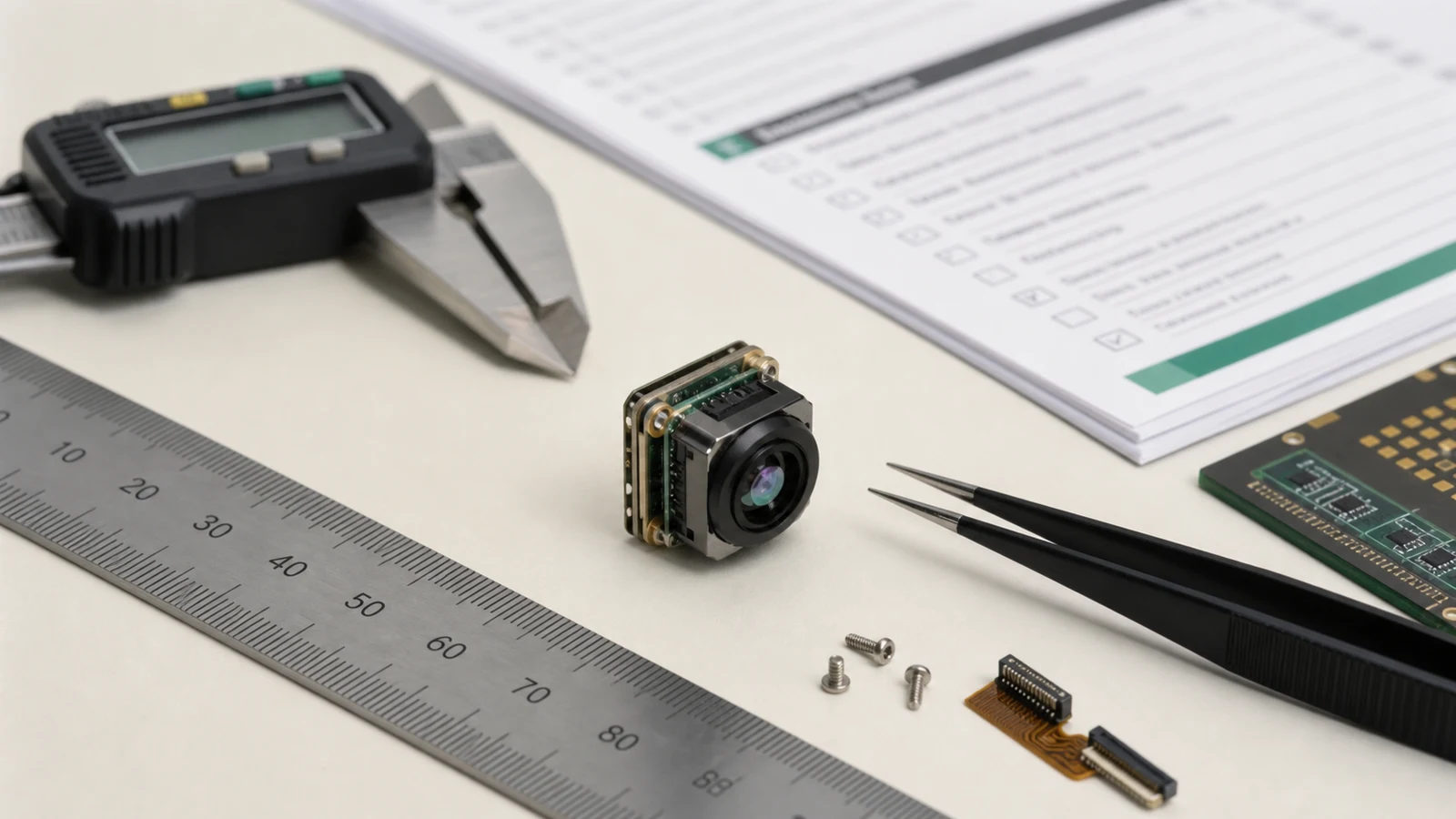
For a current same-category comparison, CAMCUDA AeroMini 640 lists a module mass of <20 g excluding the lens and flange, while the CAMCUDA SuperMini 640 LWIR Thermal Camera Module lists a bare-core mass of <3.5 g excluding the lens, flange, and user expansion board. These are different measurement scopes, so compare the complete lens, board, cable, and mount assembly before sizing the gimbal. Lower assembled mass can support the following engineering goals:
- ✅ Downsized Gimbal Actuators: Lower payload inertia may permit smaller actuators, subject to torque, balance, and wind-load testing.
- ✅ Lower Steady-State Current: Reduced corrective current can help limit motor heating; verify IMU drift over the complete flight temperature cycle.
- ✅ Slimmer Aerodynamic Cross-Sections: Smaller sensor envelopes translate directly into tight nose fairings, cutting drag during high-speed fixed-wing mapping runs.
Power Budgeting and Thermal Dissipation Under Enclosed Gimbal Conditions
Uncooled microbolometers are essentially arrays of tiny thermistors whose baseline electrical resistance shifts whenever ambient temperatures change. Inside an enclosed, sealed gimbal turret (typically rated IP64 to IP67 for rough-weather flight), any waste heat generated by video processing engines and voltage regulators gets trapped fast.
The current AeroMini 640 specification lists <0.5 W typical module consumption at 25°C, while SuperMini 640 lists ≤0.5 W typical core consumption at 25°C excluding its expansion board. Neither figure is the total payload power: include the selected interface hardware, host processor, transmission path, and regulator losses. Low core consumption helps the thermal budget, but the enclosed assembly still needs a validated heat path and temperature-rise test; it does not by itself eliminate heatsinks or cooling requirements.
2. Radiometric Optics & Sensor Architecture: Evaluating 12 µm and 8 µm VOx 640×512 Cores
An uncooled Vanadium Oxide (VOx) focal plane array operating across the 8–14 µm spectral band is the workhorse of industrial and defense UAS thermal payloads. In the field, VOx consistently outperforms older amorphous Silicon (a-Si) detectors thanks to its higher Temperature Coefficient of Resistance (TCR) and significantly lower 1/f noise. That gives you crisper scene contrast, less thermal smear during rapid yaw maneuvers, and much faster recovery during aggressive aerial sweeps.
Pixel Pitch (12 µm vs. 17 µm) and Focal Plane Array Geometry
A 640×512 array at 12 µm pitch has an active footprint of 7.68 mm × 6.144 mm; at 8 µm pitch it is 5.12 mm × 4.096 mm. AeroMini uses 12 µm pixels and SuperMini uses 8 µm pixels. The following 12 µm-versus-17 µm discussion is a general optical-design comparison, not a common specification for both products.
In the shop, that smaller footprint provides two immediate physical benefits:
- ✅ Massive Lens Weight Reduction: Matching the field of view of an older 17 µm system on a 12 µm sensor requires a significantly shorter focal length. That cuts optical glass volume and lens assembly weight by 30% to 50%.
- ✅ Compact Barrel Form Factors: Shorter back focal lengths allow standard M24 or custom micro-threaded barrels, keeping your entire payload snug and aerodynamically clean.
To see how optical footprints interface with different electrical backplanes, review our breakdown on Thermal Camera Module Interfaces: USB, MIPI, CVBS, and DVP.
NETD Sensitivity (≤30 mK vs. ≤40 mK) and Advanced Image Processing (NUC, DDE)
Noise Equivalent Temperature Difference (NETD), measured in millikelvins (mK), is the engineering benchmark for thermal sensitivity. It defines the smallest temperature difference the detector can pull out of baseline noise. When you’re flying an inspection grid on an overcast day with minimal solar loading, high NETD sensitivity makes all the difference between clear structural detail and unusable gray mush.
- ✅ ≤30 mK Sensitivity (CAMCUDA AeroMini 640): Published at 25°C, F/1.0. This is the lower listed NETD threshold in this comparison; validate useful scene contrast with the selected optics and operating conditions.
- ✅ ≤40 mK Sensitivity (CAMCUDA SuperMini 640): Published at 25°C, F1.0. NETD describes thermal sensitivity, not absolute temperature accuracy or a guarantee of detecting a particular defect.
Airborne thermal environments undergo radical scene shifts in seconds: a drone banking away from a -10°C open sky may point toward a +50°C asphalt parking lot. Evaluate correction behavior, noise reduction, and detail enhancement on the selected model and firmware rather than assuming a shared DSP or NUC implementation. SuperMini lists grayscale stretching, local contrast enhancement, temporal and spatial noise reduction, and detail and edge enhancement; those functions do not establish wire-detection or flight-obstacle-avoidance performance. You can explore more about microbolometer physics over at Wikipedia – Thermal Imaging.
Johnson Criteria, IFOV, and GSD Calculations for Aerial Inspection
Payload engineers use Ground Sampling Distance (GSD), IFOV, and target pixel coverage to estimate optical geometry before testing detection, recognition, and identification (DRI). Use the CAMCUDA Thermal Imaging Calculator to compare target size, distance, field coverage, and sensor/lens pixel sampling. These are geometric estimates, not verified DRI ranges or temperature-measurement guarantees. The table below retains illustrative 12 µm focal-length examples; it is not an AeroMini or SuperMini lens-availability list, and the legacy DRI ranges are not carried forward without target criteria and validation.
Ground Sampling Distance (GSD):
GSD = (p × H) / f
Where:
- ⚙️
p= pixel pitch (12 µm = 0.012 mm) - ⚙️
H= flight altitude above ground level (AGL) in meters - ⚙️
f= optical focal length in mm
Instantaneous Field of View (IFOV):
IFOV ≈ p / f radians = 1000 × p / f milliradians (p and f in the same units)
| Lens Focal Length | Field of View (H × V) | IFOV | Detection Range (DRI) | Recognition Range (DRI) | Identification Range (DRI) | Primary UAS Application |
|---|---|---|---|---|---|---|
| 4.1 mm | Ultra-Wide FOV | 2.93 mrad (12 µm example) | Requires validation | Requires validation | Requires validation | Close-range wide-area scene coverage |
| 4.9 mm | 76.2° × 64.2° | 2.45 mrad | Requires validation | Requires validation | Requires validation | Wide situational awareness / SAR broad search |
| 9.1 mm | 45.8° × 37.3° | 1.32 mrad | Requires validation | Requires validation | Requires validation | Solar farm inspection / General aerial mapping |
| 13 mm | 33.0° × 26.6° | 0.92 mrad | Requires validation | Requires validation | Requires validation | Industrial plant & pipeline corridor monitoring |
| 19 mm | 22.9° × 18.4° | 0.63 mrad | Requires validation | Requires validation | Requires validation | Medium-altitude high-voltage utility inspection |
| 35 mm | 12.5° × 10.0° | 0.34 mrad | Requires validation | Requires validation | Requires validation | High-altitude long-range reconnaissance / Border patrol |
3. Video Interfacing and Protocol Routing: USB UVC, MIPI CSI-2, CVBS, and Serial Control
Your hardware interface architecture determines total video pipeline latency, edge compute overhead, and telemetry routing. Depending on whether you’re building an autonomous Edge-AI tracking drone, a manual inspection rig, or a dual-stream hybrid platform, you’ll need to select your bus architecture carefully.

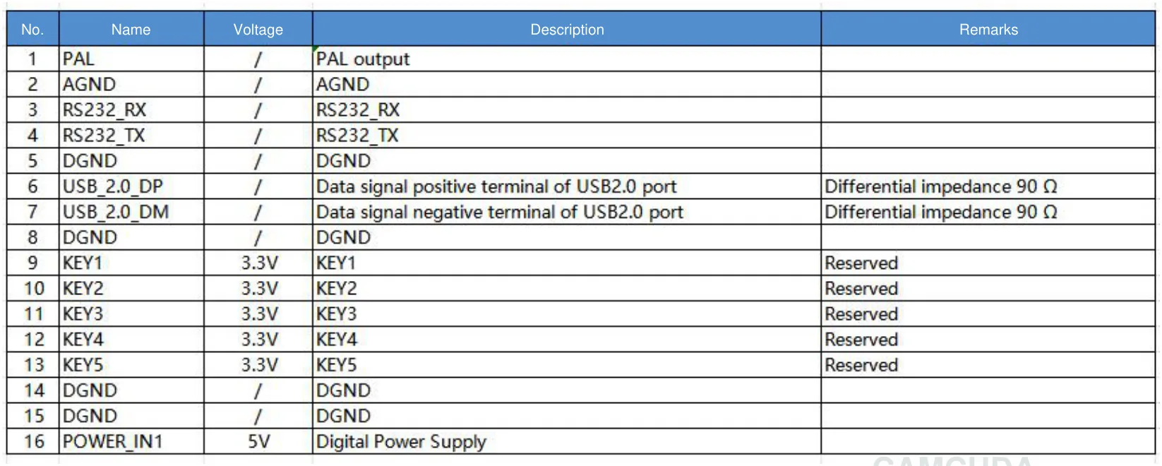
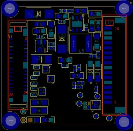
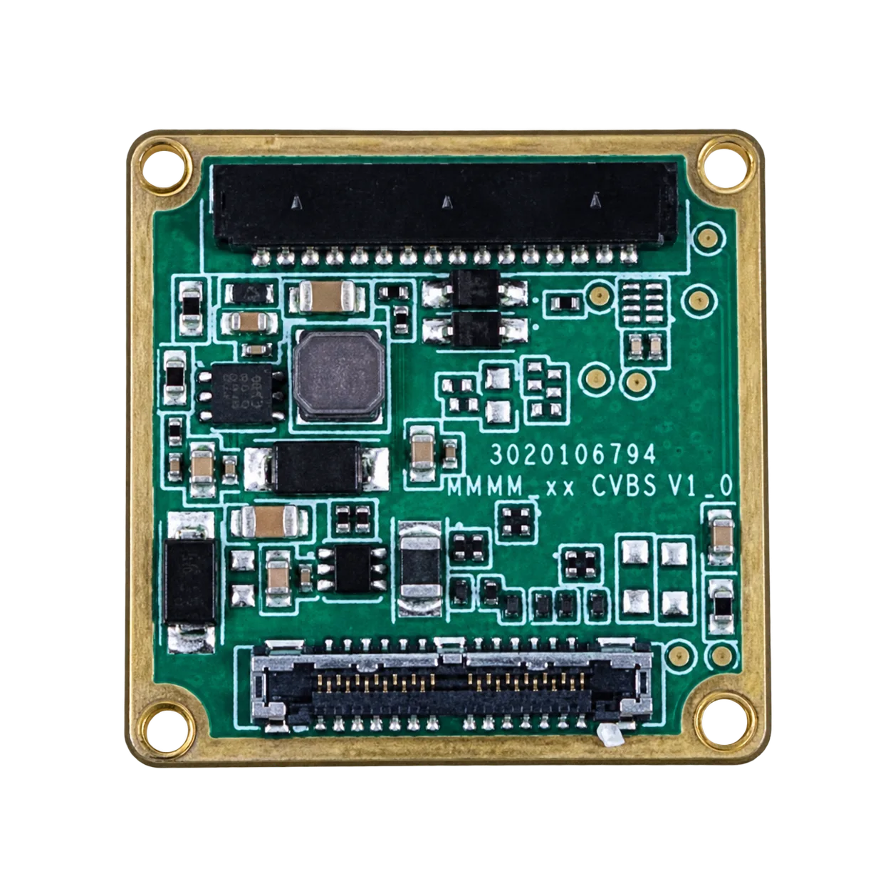
Match the tailboard before wiring: Use this schematic with the original 16-pin signal table and board layout, and compare the actual USB + CVBS + MIPI board and customer-soldered wiring cable with the supplied hardware. Pin 16 is POWER_IN1, a 5 V input; do not apply 12 V. The same tailboard’s 26-pin MIPI/DVP guide is on PDF page 4; its POWER_IN2 inputs are also 5 V only. Neither guide applies to the separate Type-C tailboard, and cable colors do not establish signal assignments.
Digital Stream Processing: USB 2.0/3.0 and MIPI for Edge AI Compute
When your thermal UAS runs onboard computer vision—like real-time human detection, brushfire perimeter tracking, or automated solar panel fault logging—you need clean digital streams:
- ⚙️ USB UVC (USB Video Class): If the selected board and firmware expose UVC, inspect the advertised formats and test the host driver. USB availability alone does not establish UVC support, radiometric RAW data, or plug-and-play compatibility with Jetson, Raspberry Pi, or x86 hosts.
- ⚙️ MIPI CSI-2: A host CSI-2 path requires matched electrical levels, lane timing, packet format, and receiver software. The product label “MIPI” alone does not establish a working CSI-2 pipeline or single-digit-millisecond latency; validate the selected model and board.
For ROS-based autonomous flight platforms, review the ROS 2 Documentation for building low-overhead image subscriber pipelines.
Legacy Analog Video (CVBS) for Low-Latency Analog Transmitters
Digital HD datalinks are great, but Composite Video (CVBS / PAL / NTSC) remains a staple on commercial flight lines for good reason:
- ✅ Analog Video Latency: An analog path can avoid a separate digital compression stage, but sensor, processing, transmission, and display delays remain. Measure end-to-end latency; neither compared module is assigned a zero-latency or sub-20 ms guarantee here.
- ✅ Graceful Link Degradation: Unlike digital links that freeze completely when RF packets drop, an analog 5.8 GHz VTX feed degrades into snow, giving the operator enough visual context to recover the aircraft.
Command, Telemetry, and Lens Control via RS-422 and Serial Bus
A reliable thermal payload needs a control link matched to its board, electrical levels, and command protocol. AeroMini lists UART, RS232, and RS422 depending on the interface board; SuperMini uses UART at 1.8 V logic. The general integration paths below require the appropriate transceiver and host software; they do not establish an included PX4, ArduPilot, MAVLink, or ROS 2 integration.
- ⚙️ RS-422 Differential Signaling: Can improve noise immunity on an appropriately designed differential link; validate cabling, termination, transceivers, and error rates in the actual airframe.
- ⚙️ UART / USB Serial Communication: Requires a compatible command set and electrical interface. Any link to PX4, ArduPilot, or MAVLink is a host-integration task and must be tested for the selected core.
4. Mechanical Hardening, Shock Isolation, and Environmental Compliance
Drones are harsh vibration environments. Catapult launches, motor rotor imbalances, prop turbulence, hard skid landings, and rapid altitude thermal shifts can destroy fragile optics and tear unhardened solder joints apart.
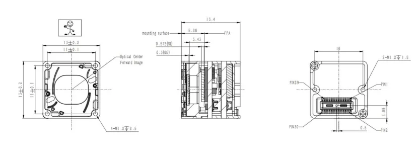
Freeze the assembled envelope: Allow for the chosen lens, interface board, connector clearance, cable bend, mount, and heat path. This drawing belongs to SuperMini and must not be used for AeroMini. The reviewed AeroMini datasheet provides interface drawings but no dimensioned complete-assembly drawing; request the drawing for the selected AeroMini lens and tailboard before enclosure tooling.
Surviving Propeller Harmonic Resonance: Configuration-Specific Vibration & Shock Tests
Spinning carbon fiber props and high-kV brushless motors generate continuous high-frequency harmonic energy along the airframe. If a thermal core lacks solid internal damping, that vibration will cause optical defocusing, split ball-grid arrays (BGAs), or trigger rolling shutter visual distortion.
Set vibration and shock acceptance criteria for the assembled flight payload. Do not reuse a legacy module’s qualification values for a replacement core:
- ⚙️ Random Vibration Reference: SuperMini’s published manual gives 2 g random vibration, 3 axes / 6 directions. Confirm the profile and assembled-payload test conditions; an AeroMini numerical qualification was not established from the reviewed specifications.
- ⚙️ Mechanical Shock Reference: SuperMini’s manual gives 6 g, 2 ms terminal-peak sawtooth, 3 axes / 6 directions. These are core references, not proof that the completed gimbal survives a particular landing or recovery event.
Configuration-Specific Operating Temperature and Thermal Drift Mitigation
For thermal UAS integration, AeroMini lists −40°C to +80°C operation. SuperMini lists −40°C to +70°C for imaging; its separate thermographic operating range is −20°C to +60°C. These are operating-environment limits, not temperature-measurement ranges or proof of radiometric drift compensation. Validate warm-up, correction behavior, and thermal stability with the final enclosure and selected version.
5. Comparative Evaluation: CAMCUDA 640×512 LWIR Modules for Thermal UAS Payloads
Choosing the right uncooled thermal core comes down to matching your airframe’s payload weight, power rails, and optical needs against real hardware. AeroMini 640 is the primary configurable integration reference here; SuperMini 640 is the same-resolution, smaller bare-core comparison. Both product families are currently featured, but that status does not establish stock or availability of every variant.
CAMCUDA AeroMini 640 LWIR Thermal Camera Core
The CAMCUDA AeroMini 640 uses a 640×512, 12 µm VOx detector with ≤30 mK NETD at 25°C, F/1.0. Its imaging-only version is 60 Hz by default, with a 30 Hz factory option; it does not measure temperature. A separate 25 Hz radiometric version is availability-enquiry only, with its interface and accuracy to be confirmed. Published <20 g weight and 21 × 21 × 28 mm dimensions exclude the lens and flange.
| Detector Specifications | |
|---|---|
| Component Model | CAMCUDA AeroMini 640 |
| Detector Type | VOx uncooled infrared focal-plane detector |
| Resolution & Pixel Pitch | 640 × 512 | 12 μm |
| Detector Frame Rate | Imaging: 60 Hz default / 30 Hz factory option; separate radiometric: 25 Hz, availability enquiry only |
| Spectral Range & NETD | 8–14 μm | ≤30 mK at 25°C, F/1.0 |
| Power, Interface & Environmental | |
| Supply Voltage & Power | 5 V or 12 V, board-dependent; POWER_IN1 / POWER_IN2 on the documented USB + CVBS + MIPI tailboard are 5 V only, never 12 V. <0.5 W typical module power at 25°C; full-kit consumption may differ. |
| Digital & Analog Video | YUV, USB, BT.656; MIPI / DVP on the documented board. CVBS / PAL / NTSC availability depends on board and firmware; confirm host compatibility. |
| Communication Interfaces | UART, RS232, or RS422 depending on the interface board |
| Mass & Dimensions | <20 g | 21 × 21 × 28 mm; excluding lens and flange |
| Operating & Storage Temp | −40°C to +80°C operating | −50°C to +85°C storage |
| Vibration & Shock Rating | Numerical qualification not established from the reviewed AeroMini specifications; request the selected assembly’s test report. |
CAMCUDA SuperMini 640 LWIR Thermal Camera Module
The CAMCUDA SuperMini 640 (CC-SM640-I50) is the 50 Hz imaging-only comparison, with a 640×512, 8 µm VOx detector and ≤40 mK NETD at 25°C, F1.0. Its <3.5 g, 13 × 13 × 13.4 mm bare core excludes the lens, flange, and user expansion board. The separate SuperMini 640T is the 30 Hz thermographic model; temperature ranges, accuracy, and temperature-data output do not apply to the imaging-only 640. Confirm the selected lens, interface, supplied items, and availability by quotation.
| Core Performance & Electrical | |
|---|---|
| Resolution & Pixel Pitch | 640 × 512 | 8 μm VOx focal-plane array |
| Thermal Sensitivity (NETD) | ≤40 mK at 25°C, F1.0; not temperature-measurement accuracy |
| Power Input & Consumption | MAIN_POWER 3.8–5.2 V plus separate regulated +3.3 V and +1.8 V rails; confirm noise limits and sequencing. ≤0.5 W typical core power at 25°C, excluding expansion board. |
| Video Output Interface | 8-bit LVCMOS / BT656 and 2-lane MIPI; BT656 and MIPI cannot operate simultaneously. Optional USB expansion board; CVBS requires an external video-buffer IC. UART control is 1.8 V logic. |
| Image Processing & Delay | Grayscale stretching, local contrast enhancement, temporal/spatial noise reduction, and detail/edge enhancement; no numerical end-to-end latency established here. |
| Module Mass & Operating Temp | <3.5 g excluding lens, flange, and expansion board | imaging −40°C to +70°C; thermography −20°C to +60°C |
| Published F1.0 Athermal Optics & Assembly Scope | |
| 3.7 mm Lens Option | 90.0° × 68.2° FOV | 2.16 mrad published IFOV |
| 6.1 mm Lens Option | 46.6° × 37.6° FOV | 1.31 mrad published IFOV |
| 8.7 mm Lens Option | 40.0° × 32.2° FOV | 0.92 mrad published IFOV |
| 11 mm Lens Option | 24.9° × 20.0° FOV | 0.73 mrad published IFOV |
| Configured Assembly | Core: 13 × 13 × 13.4 mm excluding lens, flange, and expansion board; confirm final envelope and target performance with the chosen optics. |
Engineering Comparison Matrix
| Specification Parameter | CAMCUDA AeroMini 640 | CAMCUDA SuperMini 640 | Thermal UAS Design Consideration |
|---|---|---|---|
| Detector Resolution | 640 × 512 | 640 × 512 | Compare actual lens, target size, distance, and pixel coverage |
| Pixel Pitch | 12 µm | 8 µm | The same focal length gives different sampling and field coverage |
| NETD Sensitivity | ≤30 mK at 25°C, F/1.0 | ≤40 mK at 25°C, F1.0 | AeroMini has the lower listed threshold; NETD is not temperature accuracy |
| Module Mass | <20 g excluding lens and flange | <3.5 g excluding lens, flange, and expansion board | Different measurement scopes; compare assembled payloads |
| Power Consumption | <0.5 W typical at 25°C; full-kit consumption may differ | ≤0.5 W typical core at 25°C; expansion board excluded | Budget board, host, link, and regulator losses separately |
| Input Voltage Range | 5 V or 12 V by board; USB + CVBS + MIPI tailboard POWER_IN1 / POWER_IN2: 5 V only | MAIN_POWER 3.8–5.2 V plus regulated +3.3 V and +1.8 V rails | Use verified regulated supplies; do not assume a direct battery connection |
| Video Output | Board-dependent USB / YUV / BT.656, MIPI / DVP, and CVBS | LVCMOS / BT656 or 2-lane MIPI; optional USB board; external CVBS buffer required | Verify output format, receiver and firmware; no universal UVC guarantee |
| Operating Temperature | −40°C to +80°C | Imaging −40°C to +70°C; thermography −20°C to +60°C | Validate the selected model in the completed enclosure |
6. System Integration Architecture & Software Stack
Getting a thermal core running reliably in an airframe means tying mechanical balance, clean electrical harnesses, and software drivers together properly.
Gimbal Mount Mechanical Integration & Slip-Ring Cable Routing
Continuous 360-degree yaw tracking may use a miniature slip ring for power, video, and telemetry. Apply only the paths supported by the selected board: RS422 is board-dependent on AeroMini, while SuperMini’s 1.8 V UART needs the appropriate external interface. When routing a compatible wiring harness:
- ⚙️ Differential Routing for RS-422: Always twist your
TX+/TX-andRX+/RX-conductor pairs together to cancel out inductive motor commutation spikes. - ⚙️ Shielded USB Routing: Keep high-speed USB data runs under 15 cm using foil-shielded micro-coax lines to prevent radiation that can desensitize 2.4 GHz control receivers.
- ⚙️ Common Ground Plane: Tie power return and logic ground together at a single, solid reference star point on your payload carrier board to eliminate ground loops.
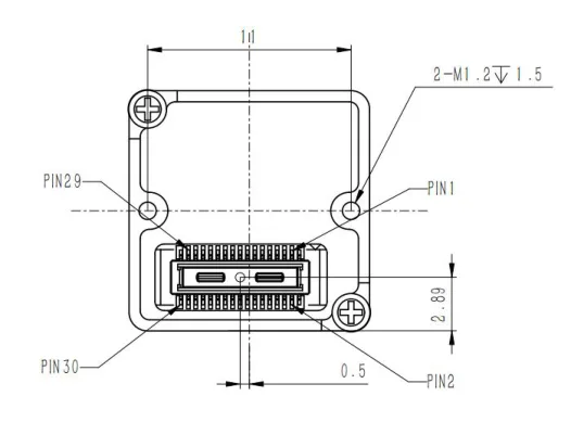
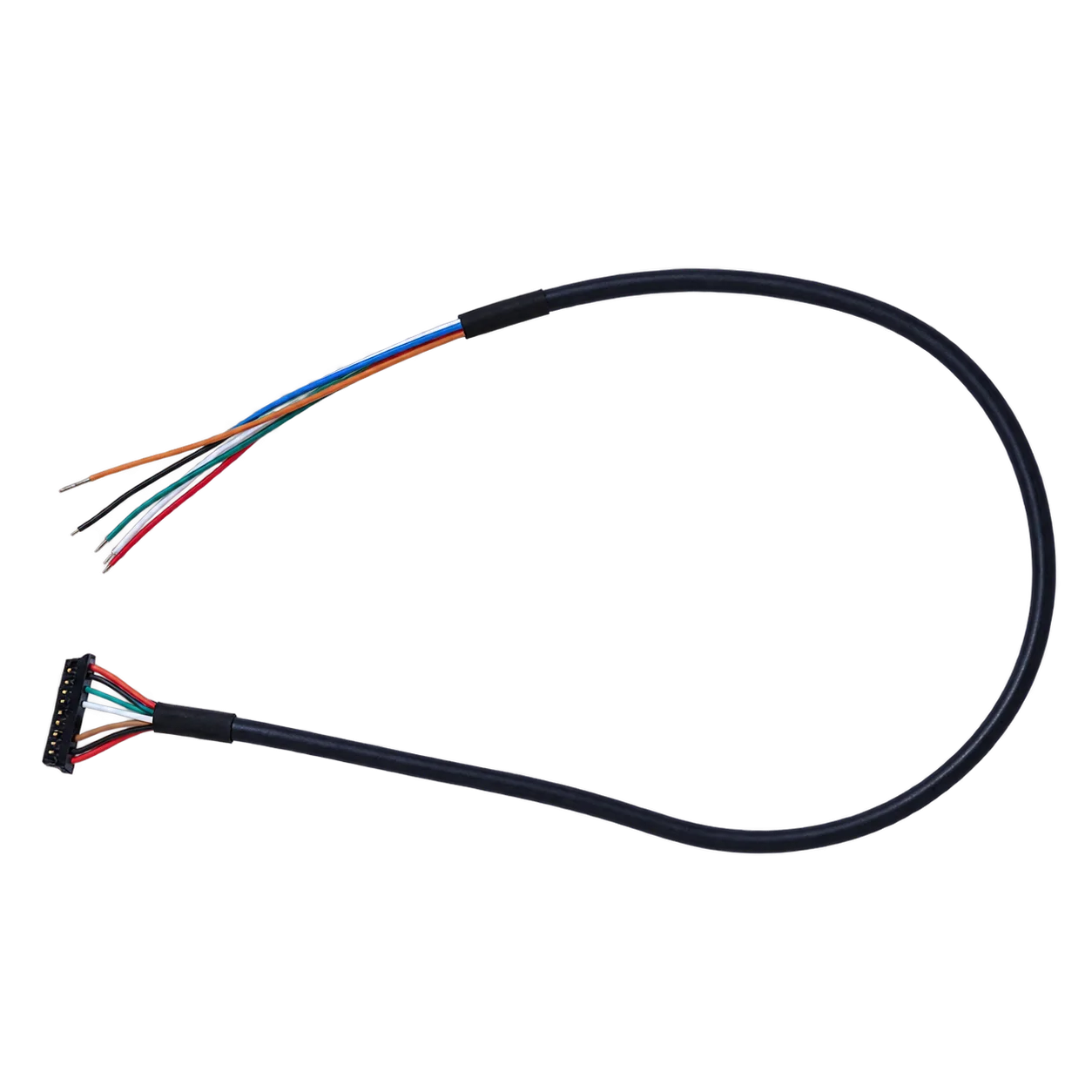
Keep the core and expansion-board harnesses separate: This Hirose DF40C-30DP-0.4V(51) interface is not the optional 4-pin USB board, an AeroMini connector, or a Type-C cable pinout. The bare core requires MAIN_POWER 3.8–5.2 V plus regulated +3.3 V and +1.8 V rails; follow the manual’s power requirements on PDF page 8. UART is 1.8 V logic, with TX/RX referenced to the core, and CVBS requires an external video-buffer IC. Disconnect power before connecting or disconnecting cables.
ROS 2 / Linux Driver Pipeline for Thermal Data Processing
The commands below are a generic host-side example only, applicable after the selected USB assembly has been verified to expose a compatible UVC/V4L2 device. They are not an included AeroMini or SuperMini ROS 2 SDK, and do not establish radiometric, 14-bit, or 16-bit output. Query the actual formats before selecting resolution, pixel format, or frame rate:
# Query V4L2 device formats on companion computer
v4l2-ctl --device=/dev/video0 --list-formats-ext
In a ROS 2 environment with verified driver support, a v4l2_camera configuration can be tested as a host integration example. The 50.0 value below is illustrative, not an AeroMini frame-rate specification; replace it and the pixel format with values actually supported by the selected output. YUYV image data alone is not calibrated temperature data:
# ros2_thermal_config.yaml
v4l2_camera_node:
  ros__parameters:
    video_device: "/dev/video0"
    image_size: [640, 512]
    pixel_format: "YUYV"
    camera_frame_id: "thermal_optical_frame"
    framerate: 50.0
After validating capture, host software may process thermal imagery for tracking and reporting. ROI temperature calculations require an independently confirmed thermographic model, temperature-data path, and calibration workflow. MAVLink telemetry and autopilot behavior need separate host-side implementation and end-to-end tests.
For pinout drawings, CAD step files, or custom optical coatings, reach out directly via the CAMCUDA Contact & RFQ Portal. For more technical teardowns, check out the CAMCUDA Engineering Blog Archive.
7. Frequently Asked Questions (FAQ)
Why is a 640×512 resolution module essential for commercial thermal UAS mapping in utility and solar inspections?
How do module weight and interface options impact thermal UAS gimbal design?
How do we choose the right factory lens focal length for wildlife tracking versus structural inspection?
📚 References & Further Reading
- Industry Standard: ROS 2 Documentation
- Scientific Principles: Wikipedia – Thermal Imaging
- Related Guide: Thermal Camera Module Interfaces: USB, MIPI, CVBS, and DVP
- Technical Insights: CAMCUDA Engineering Blog Archive
- OEM Engineering Support: CAMCUDA Contact & Custom Integration RFQ