Drone with Night Vision: Thermal LWIR vs. Low-Light Sensor Guide for Integrators
Drone with Night Vision: Thermal LWIR vs. Low-Light Sensor Guide for Integrators
Operating unmanned aerial systems in pitch-black environments, dense fog, and degraded visual conditions will test every limit of your optical payload. When you are spec’ing an airborne drone with night vision for mission-critical jobs—whether that is utility inspection, perimeter security, tactical search and rescue (SAR), or persistent intelligence, surveillance, and reconnaissance (ISR)—you run straight into a wall of confusing vendor terminology. Integrators get caught wrestling with the practical divide between active/ambient low-light CMOS sensors working in the near-infrared band (NIR, 750 nm to 1000 nm) and passive uncooled long-wave infrared microbolometers (LWIR, 8 µm to 14 µm).
Here’s the deal: picking the wrong imaging setup will trash your mission before the drone clears its first waypoint. Active near-infrared camera setups get completely blinded by propwash kicking up dirt, dust, and moisture into your optical path. Ambient low-light CMOS chips simply fall apart into digital noise the second ambient illumination drops below basic physical lux thresholds. Building a reliable airborne vision payload means cutting through marketing claims and running the hard math on radiant flux physics, optical aperture constraints, size, weight, power, and cost (SWaP-C) trade-offs, and rock-solid digital video bus pipelines.
Table of Contents
- 👉 1. Radiometric Physics: LWIR Thermal vs. Low-Light CMOS & NIR
- 👉 2. Comparative Engineering Trade-Off Matrix
- 👉 3. SWaP-C Optimization for Drone Payloads
- 👉 4. Digital Video Bus, Latency, and Interface Standards
- 👉 5. Optics, Germanium Elements, and Johnson’s Criteria Calculations
- 👉 6. Ground-to-Air Synergy: Correlating Aerial Thermal Payloads with Ground Assets
- 👉 7. Enterprise Thermal System Specifications
- 👉 8. Integration and Procurement FAQ
1. Radiometric Physics: LWIR Thermal vs. Low-Light CMOS & NIR
When you sit down at the bench to architect an airborne electro-optical payload, your first step is understanding how your sensor interacts with the electromagnetic spectrum. You are either collecting reflected ambient photons or measuring directly emitted radiant heat flux. There is no middle ground.
Digital low-light night-vision cameras use Back-Illuminated (BSI) or Stacked CMOS active-pixel sensors designed to pull decent quantum efficiency (QE) out of the near-infrared band (750 nm to 1000 nm). These chips require some ambient photons to bounce off the subject—starlight, skyglow, or supplemental 850 nm / 940 nm infrared LED illuminators. If you have clear skies and a sliver of starlight (around 0.001 lux), high-grade low-light CMOS cameras output crisp monochrome video showing text, paint markings, and fine structural borders. But take that sensor into true zero-lux conditions—like under heavy cloud cover, thick tree canopies, or unlit tunnels—and the signal-to-noise ratio (SNR) plummets into a useless sea of fixed-pattern and dark-current shot noise.
Bolting active NIR LED spotlights to your drone looks tempting on paper, but it causes huge headaches in flight. The inverse-square law is brutal: double your standoff distance and you need four times the optical power to light up the target. Even worse, your drone’s props create high-velocity downdrafts that kick up dust, pollen, and water vapor right in front of your glass. The moment that active infrared beam hits those airborne particles, Mie scattering bounces the light straight back into the sensor, washing out the entire image with blinding white glare. On top of that, your active IR beam acts like a giant beacon to anyone on the ground holding an entry-level night-vision monocular.
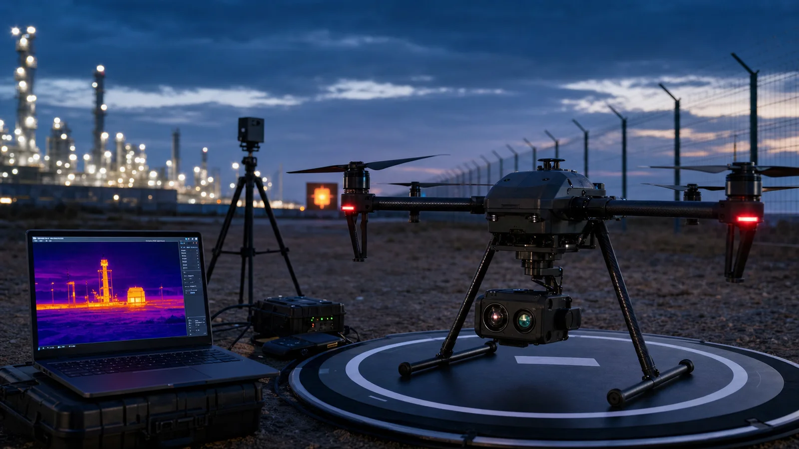
Long-wave infrared (LWIR) microbolometers skip the illumination problem entirely by working inside the 8.0 µm to 14.0 µm atmospheric transmission band. Instead of trying to catch stray bounced light, LWIR arrays passively read blackbody radiant heat governed by the Stefan-Boltzmann Law:
j* = ε · σ · T⁴
In this equation, j* is total radiant emittance, ε is the target surface emissivity, σ is the Stefan-Boltzmann constant (5.670374 × 10⁻⁸ W·m⁻²·K⁻⁴), and T represents absolute temperature in Kelvin. Modern Vanadium Oxide (VOx) uncooled microbolometers absorb this long-wave energy on microscopic suspended membrane bridges. As those bridges heat up, their electrical resistance changes across every pixel (typically packed at a tight 12 µm pitch), which an underlying CMOS Readout Integrated Circuit (ROIC) converts into a clean thermal map.
Because everything in the real world warmer than absolute zero pumps out radiant heat, LWIR microbolometers work in total, 100% pitch-black darkness (0.0000 lux) without a single spotlight. Long-wave infrared wavelengths (8–14 µm) are much wider than airborne dust motes, micro-droplets, and smoke particulates, letting the signal cut straight through haze, wildfire smoke, light fog, and brush with almost zero optical scatter. When engineers need to pair long-wave thermal detection with high-resolution visible cameras, they typically turn to dedicated drone camera integration modules to synchronize the data streams without adding payload bloat.
2. Comparative Engineering Trade-Off Matrix
Balancing sensor sensitivity, atmospheric transmission, mechanical packaging, and onboard battery draw is the core challenge of payload design. The table below breaks down the hard physical parameters across digital low-light CMOS, uncooled VOx LWIR, and cryocooled MWIR systems.
| Engineering Dimension | Digital Low-Light CMOS (NIR) | Uncooled LWIR Thermal (VOx) | Cooled MWIR (3–5 µm) System |
|---|---|---|---|
| Operational Illuminance | 10⁻³ to 10⁵ Lux (Fails at 0 Lux without LEDs) | 0.00 Lux (Completely Passive Emission) | 0.00 Lux (Completely Passive Emission) |
| Spectral Band | 0.4 µm to 1.0 µm (Visible to NIR) | 8.0 µm to 14.0 µm (LWIR) | 3.0 µm to 5.0 µm (MWIR) |
| Standard Pixel Pitch | 1.4 µm to 2.9 µm | 12 µm (State-of-the-art uncooled) | 10 µm to 15 µm |
| Thermal Sensitivity (NETD) | Not Applicable (Photon flux dependent) | ≤ 20 mK to 40 mK | < 15 mK (Cryocooled) |
| Obscurant Penetration | Poor; severe backscatter from artificial light | High (Porous through fog, smoke, haze) | Extreme (High atmospheric standoff performance) |
| Target Identification | High detail (Facial features, painted text) | Silhouettes & thermal delta patterns | High-resolution geometric heat profiles |
| Core Power Draw | 1.0 W to 2.5 W | 1.2 W to 3.5 W | 8.0 W to 25.0 W (Stirling cryocooler engine) |
| Core Sensor Weight | < 40 g | 30 g to 90 g | 350 g to 1500 g |
| Optical Material Requirement | Standard Optical Glass (BK7, Fused Silica) | Germanium (Ge), Chalcogenide (GASIR) | Silicon (Si), Germanium, Sapphire |
3. SWaP-C Optimization for Drone Payloads
Every gram counts in aerial robotics. Integrating night-vision payloads into Class 1 (micro), Class 2 (small), and Class 3 (tactical) multi-rotor or fixed-wing airframes requires strict SWaP-C control. In the shop, we use a simple rule of thumb: hanging an extra 50 grams of dead weight on a small enterprise quadcopter cuts useful flight endurance by 1.2 to 1.8 minutes. That lost time directly reduces your search area per battery set.
Gimbal dynamics make packaging even trickier. A 3-axis brushless gimbal demands that the optical payload’s center of gravity (CoG) lands dead center across the intersecting pitch, roll, and yaw motor axes. Moving from older 17 µm microbolometers down to modern 12 µm pixel sensors lets you run smaller Germanium front elements while keeping equivalent optical magnification. But fast thermal glass—like a 70 mm F1.0 Germanium lens—is notoriously dense and can easily push past 200 grams on its own. That front-heavy mass means adding rear brass counterweights and dialing up your Field-Oriented Control (FOC) motor torque to fight aerodynamic shear forces during aggressive flight banking.
Thermal management inside an enclosed gimbal ball is another common failure point. An uncooled VOx core pulls between 1.2 W and 3.5 W under steady-state operation. Because microbolometer pixels detect heat via tiny resistance shifts, internal casing heat will cause the focal plane array to drift. If the core has nowhere to sink that heat, the image degrades with heavy spatial noise. You need dedicated copper or aluminum heat straps leading from the sensor chassis to the outer payload shell. Letting downwash from the rotors pull heat off the outer casing keeps the core thermally stable, stopping the internal mechanical shutter from constantly dropping down for Non-Uniformity Correction (NUC) cycles that freeze your live video feed during an active target lock.
4. Digital Video Bus, Latency, and Interface Standards
If you are building an airborne platform for fast automated tracking or precise pilot control, your video pipeline must be rock solid. Any video transmission lag over 60 milliseconds introduces pilot overcorrection and causes onboard AI vision algorithms to lose track of fast-moving vehicles.
Routing raw radiometric data and processed video from the sensor core to the flight companion computer requires a carefully chosen hardware bus:
- ⚙️ MIPI CSI-2 (Camera Serial Interface): The top choice for tight embedded integrations. MIPI CSI-2 pipes uncompressed RAW14 radiometric pixel data or processed 8-bit/16-bit streams straight into onboard compute boards (like NVIDIA Jetson Orin or Rockchip modules) with sub-millisecond pipeline latency. This direct lane gives your edge-AI neural networks full-resolution data for object classification.
- ⚙️ CoaXPress (CXP): Ideal for long-range tactical gimbals and tethered drones where signals pass through slip rings. CXP handles high-speed multi-gigabit transfers over tiny micro-coaxial cables. Make sure your hardware is verified under the JIIA CoaXPress Certification Program to avoid dropped packets under vibration.
- ⚙️ USB3 Vision / UVC: The standard for modular, quick-swap payload pods. It gives you solid plug-and-play Linux driver support, but beware: USB kernel buffers typically add 15 ms to 45 ms of transmission latency that must be accounted for in visual servoing loops.
- ⚙️ Analog CVBS (NTSC/PAL): Old tech, but still the gold standard for high-speed tactical FPV interceptors. Because an analog composite signal skips digital compression and frame-buffering stages, you get zero-latency video over 5.8 GHz video transmitters.
5. Optics, Germanium Elements, and Johnson’s Criteria Calculations
Standard optical glasses like BK7 and fused silica are dead opaque to long-wave thermal radiation, absorbing 8–14 µm light completely. Thermal drone payloads must use specialized optical materials, primarily mono-crystalline Germanium (Ge). Germanium has a massive refractive index of roughly 4.0 at 10 µm, which lets optical engineers design compact, short-focal-length lens assemblies with minimal spherical aberration. Because raw Germanium is soft and vulnerable to flying debris, external lens faces require Diamond-Like Carbon (DLC) hard coatings, while internal elements use multi-layer Anti-Reflective (AR) coatings. Precision optical houses like Ophir IR Optics supply these custom-engineered, ruggedized LWIR lens assemblies specifically for UAV applications.
To calculate real-world target acquisition ranges from an airborne platform, we rely on classical Johnson’s Criteria. This method links your focal plane array pixel pitch, lens focal length, and target dimensions to define operational detection, recognition, and identification (DRI) distances:
- ✅ Detection (D): Requires 1.5 pixels (0.75 line pairs) across the target’s critical dimension. Enough to tell an object is present against background terrain.
- ✅ Recognition (R): Requires 6.0 pixels (3.0 line pairs) across the critical dimension. Enough to classify what you are looking at (e.g., distinguishing a person from a deer).
- ✅ Identification (I): Requires 12.0 pixels (6.0 line pairs) across the critical dimension. Enough to confirm detailed target traits (e.g., distinguishing an armed subject from an unarmed utility worker).
The mathematical formula to determine operational range (R) is:
R = (f · H_c) / (N · p)
Where:
- ⚙️ f = Lens focal length in millimeters (mm)
- ⚙️ H_c = Critical target dimension in meters (standard NATO human target = 1.8 m; light vehicle = 2.3 m)
- ⚙️ N = Required pixel count across the target (Detection = 1.5, Recognition = 6.0, Identification = 12.0)
- ⚙️ p = Detector pixel pitch in millimeters (e.g., a 12 µm pitch = 0.012 mm)
Practical Drone Sensor Calculation Example:
Let’s run the numbers for an airborne payload using a 640 × 512 VOx sensor with a 12 µm pixel pitch and a 70 mm F1.0 Germanium objective, looking at a standing human (H_c = 1.8 m):
Detection Distance (N = 1.5):
R_det = (70 mm × 1.8 m) / (1.5 × 0.012 mm) = 126 / 0.018 = 7,000 meters
Recognition Distance (N = 6.0):
R_rec = (70 mm × 1.8 m) / (6.0 × 0.012 mm) = 126 / 0.072 = 1,750 meters
Identification Distance (N = 12.0):
R_id = (70 mm × 1.8 m) / (12.0 × 0.012 mm) = 126 / 0.144 = 875 meters
Keep in mind that field conditions reduce these numbers based on atmospheric transmission (τ_atm), ambient humidity, and lens aperture. Fast F1.0 Germanium optics pull in 44% more thermal radiation than slower F1.2 lenses, providing clear thermal contrast when operating in humid climates with low thermal variance.
6. Ground-to-Air Synergy: Correlating Aerial Thermal Payloads with Ground Assets
Real-world industrial operations do not rely solely on drones. For continuous industrial security, critical infrastructure sweeps, and search grids, drones act as wide-area searchers that hand off targets to ground personnel running high-resolution handheld thermal systems.
In this workflow, the drone patrols at higher altitude with a wider field-of-view lens (25 mm to 35 mm), scanning square kilometers of rugged terrain to pinpoint thermal anomalies. The moment a target is spotted, precise coordinates are pushed across a tactical network to ground teams. Field personnel equipped with ruggedized handheld thermal binoculars or long-range monoculars (running 50 mm or 70 mm F1.0 optics) confirm and track the target from the ground. This team setup keeps your drone from having to burn battery hovering low over the objective.
For a deeper look at field-tested hardware setups, check out our operational guide covering outdoor field thermal imaging workflows designed for coordinated air and ground deployment.
7. Enterprise Thermal System Specifications
The following hardware systems represent production-grade thermal platforms built for demanding field verification, perimeter surveillance, and ground-support missions.
Product Profile: CAMCUDA Ura-Y 640 Handheld Thermal Binoculars
The CAMCUDA Ura-Y Series is an uncooled 640×512 handheld thermal binocular built for long-range observation, perimeter security, and field search. Driven by a 640×512 VOx uncooled microbolometer with a 12 µm pixel pitch and a 50 fps refresh rate, this unit is paired with a heavy-duty 70 mm F1.0 Germanium objective. The result is a sharp, narrow 7.0° × 4.8° field of view, ideal for spotting distant thermal anomalies across vast open ranges.
| Technical Parameter | Specification Value |
|---|---|
| Sensor Type | VOx uncooled sensor |
| Array Resolution | 640 × 512 |
| Pixel Pitch | 12 µm |
| Frame Rate | 50 fps |
| Optical Objective Lens | 70 mm F1.0 |
| Field of View (FOV) | 7.0° × 4.8° |
| Weight Class | Approx. 1 kg class |
The Ura-Y platform is built to handle rugged field inspection and long-standoff perimeter scanning. Full technical sheets and NDAA compliance statements are available on request during project evaluations.
View Product Details & Pricing ➔
Product Profile: CAMCUDA FieldView Handheld Thermal Viewer
The CAMCUDA FieldView Handheld Thermal Viewer is a compact infrared observation system engineered for high-mobility field teams doing outdoor tracking, infrastructure audits, and wildlife surveys. Available in both 384×288 and 640×512 configurations on a 12 µm VOx core, it runs across the 8–14 µm spectral band at 50 Hz. Featuring an impressive thermal sensitivity rating of NETD ≤ 20 mK (@25°C, F#1.0, 25Hz), it offers flexible 25 mm, 35 mm, or 50 mm F1.0 lens setups inside a lightweight ~550 g housing.
| Technical Parameter | Specification Value |
|---|---|
| Sensor Core Architecture | VOx uncooled sensor, 8 to 14 µm |
| Resolution Paths | 384 × 288 @ 12 µm / 640 × 512 @ 12 µm |
| Frame Refresh Rate | 50 Hz |
| Lens Configurations | 25 mm / 35 mm / 50 mm F1.0 options |
| Thermal Sensitivity (NETD) | ≤ 20 mK (@25°C, F#1.0, 25Hz) |
| Chassis Weight | Approx. 550 g class |
The FieldView unit is an ideal choice for mobile operators who need top-tier thermal sensitivity without the bulk of heavy observation gear. Complete spec sheets, technical integration manuals, and NDAA certificates are available for your RFQ process.
View Product Details & Pricing ➔
8. Integration and Procurement FAQ
What is the primary difference between a digital night vision drone and a thermal imaging drone?
Why do consumer drones with active IR night vision struggle in professional search and inspection missions?
What SWaP parameters are most critical when integrating a thermal sensor into a UAV gimbal payload?
How does sensor frame rate (9Hz vs. 50Hz) impact UAV flight stability and computer vision tracking?
What compliance and trade regulations govern the procurement of high-performance thermal cores?
📚 References & Further Reading
- Industry Standard: JIIA CoaXPress Certification Program
- Optical Component Standards: Ophir IR Optics Specialized Thermal Optics
- Related Payload Guide: CAMCUDA Airborne Drone Camera Modules
- Deployment Guide: Outdoor Field Thermal Imaging Workflows
- Procurement Governance: CAMCUDA Hardware Compliance & Terms of Service