Cheap IR Camera Guide: Sourcing Cost-Effective LWIR Thermal Modules for OEM & Embedded Systems
Cheap IR Camera Guide: Sourcing Cost-Effective LWIR Thermal Modules for OEM & Embedded Systems
If you’ve spent any time sourcing a cheap ir camera for an embedded build or an industrial product line, you already know the market is a minefield of misleading specs and outright bogus claims. In industrial design, embedded vision, and unmanned robotics, “cheap” must never mean ignoring basic physics. Here’s the deal: there is an absolute physical divide between a budget-grade converted Silicon CMOS sensor catching reflected Near-Infrared (NIR) light and a true uncooled Long-Wave Infrared (LWIR) microbolometer capturing emissive thermal signatures from 8 µm to 14 µm. Pick the wrong modality on paper, and you are headed for catastrophic field failures, massive thermal drift, target misidentification, and a gut-wrenching board redesign cycle.
True cost-efficiency in modern infrared engineering comes down to uncompromising Size, Weight, Power, and Cost (SWaP-C) optimization. Getting an economical thermal imaging sub-assembly onto your bill of materials (BOM) means striking a pragmatic balance: core resolution (like entry-level 160×120 thermal sensing versus 640×512 high-resolution aerial mapping), detector pixel pitch, optical glass chemistry, host communication topologies (SPI, USB, RS-422, CVBS), and onboard hardware image processing pipelines. This teardown walks you through the physics, detector architectures, optical economics, interface engineering, and field-proven hardware modules for drone gimbals, smart appliances, process monitoring, and edge-AI vision rigs.
Sales contributors: Vivian, Lena and Sophie
Table of Contents
- 👉 1. Deconstructing the “Cheap IR Camera”: Physics, Wavelengths, and Sensor Modalities
- 👉 2. Detector Architectures: Microbolometers vs. Thermopiles vs. Converted CMOS
- 👉 3. SWaP-C Optimization: Engineering Cost-Effective Thermal Payloads
- 👉 4. Host Integration: Low-Power SPI, High-Bandwidth USB, and Industrial Telemetry
- 👉 5. Production-Ready LWIR Modules: Technical Evaluation & Spec Matrix
- 👉 6. Optics, Materials, and Radiometry: Managing Bill-of-Materials (BOM) Costs
- 👉 7. OEM Sourcing and Implementation Checklist
- 👉 8. Deep-Dive Frequently Asked Questions (FAQ)
1. Deconstructing the “Cheap IR Camera”: Physics, Wavelengths, and Sensor Modalities
The electro-optical spectrum spans several distinct operational bands, each ruled by its own semiconductor physics, optical transmission windows, and atmospheric quirks. When hunting down a budget-friendly infrared module, your engineering team has to look past marketing buzzwords and match the sensor’s physical bandgap directly to the problem you are solving.
Planck’s Radiation Law tells us that every object above absolute zero emits electromagnetic radiation with a spectral radiance determined entirely by its thermodynamic temperature. For everyday terrestrial machinery, human targets, and ambient outdoor environments sitting between -40°C and +150°C (233 K to 423 K), peak blackbody emission falls squarely inside the Long-Wave Infrared (LWIR) band between 8 µm and 14 µm. You can calculate this directly from Wien’s Displacement Law:
λmax = b / T = (2897.8 µm·K) / 300 K ≈ 9.66 µm
The Near-Infrared (NIR) Band (0.75 µm to 1.0 µm)
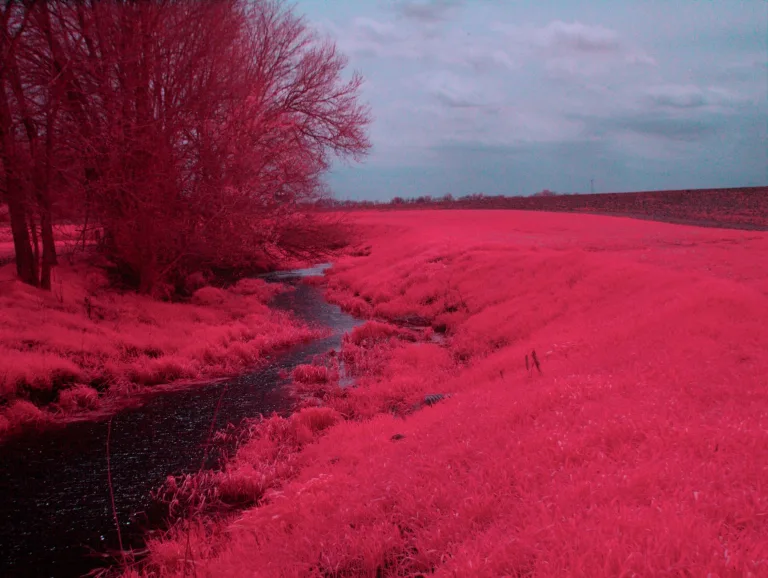
In low-cost consumer dashcams and entry-level security gear, anything branded as an “IR night vision camera” is almost always a standard Silicon CMOS sensor with the internal IR-cut hot mirror pulled off. Standard Silicon has an electronic bandgap around 1.1 eV, meaning it physically stops responding to photons past roughly 1.05 µm. These sensors do not see thermal energy; they detect reflected photons, which means they are dead in the water without active illumination from 850 nm or 940 nm LEDs.
That might work for a nursery monitor, but in the field, it is a non-starter. NIR setups cannot measure heat or surface temperature differentials, they get completely blinded by smoke, fog, and dust, and they reveal your position instantly if stealth or power preservation matters.
The Short-Wave (SWIR) and Mid-Wave Infrared (MWIR) Bands (1.4 µm to 5.0 µm)
SWIR imagers (1.4–3.0 µm) use Indium Gallium Arsenide (InGaAs) focal planes to pick up reflected ambient nightglow or laser pointers through heavy atmospheric haze. MWIR imagers (3.0–5.0 µm) rely on Indium Antimonide (InSb) or Mercury Cadmium Telluride (MCT) sensors to track high-temperature exhaust and extreme thermal plumes over long distances. But here’s the catch: MWIR systems require active Stirling cryogenic cooling engines running at 77 K. That pumps the unit cost past ten grand and ties your system reliability to a mechanical cooler with a finite operational lifespan.
The Long-Wave Infrared (LWIR) Band (8.0 µm to 14.0 µm)
LWIR is where real-world thermal imaging happens. Operating right in Earth’s primary atmospheric transmission window, an uncooled LWIR core measures the raw, self-emitted photon flux driven by the kinetic molecular vibrations of the scene itself. Day, night, zero-lux darkness, thick smoke, or driving rain—an LWIR sensor sees right through it without any active illuminators. For system architects designing autonomous mobile robots or aerial vision payloads, checking out real-world commercial and industrial thermal applications demonstrates how picking the right spectral band makes or breaks downstream computer vision performance.
2. Detector Architectures: Microbolometers vs. Thermopiles vs. Converted CMOS
Hitting your target BOM cost means choosing an architecture that hits your resolution and update rate requirements without paying for semiconductor real estate you don’t need.
Thermopile Arrays: Ultra-Low-Cost Parametric Sensing
Thermopiles leverage the thermoelectric Seebeck effect, stringing together series arrays of thermocouple junctions across p-type and n-type semiconductor legs. When incoming LWIR photons heat the active junction relative to a cold reference junction, it produces a proportional open-circuit voltage:
Vout = N · S · ΔT
Where N is your thermocouple count and S is the Seebeck coefficient. Thermopile arrays bring solid perks for low-level presence triggers: no mechanical shutter required, tiny power draw (<20 mW), and simple I2C readouts. But on the bench, their physical mass causes high thermal time constants. That caps your frame rate below 8 Hz, yields poor thermal sensitivity (NETD > 100–150 mK), and leaves you with tiny grid resolutions (from single-pixel spot sensors up to 32×24 or 80×62 arrays). Use them for HVAC occupancy sensing or bulk fire alarms, but don’t expect them to track moving targets or outline machine edges.
Uncooled Microbolometer Focal Plane Arrays (FPAs)
For actionable thermal vision, microbolometers are the gold standard. A microbolometer array consists of MEMS bridge structures suspended above a Silicon Read-Out Integrated Circuit (ROIC). Each pixel features an IR absorber membrane suspended on microscopic legs inside a vacuum package, creating an isolated thermal pocket.
As LWIR photons hit the suspended membrane, its temperature changes, shifting the electrical resistance of the thin-film thermistor. The ROIC measures this shift via the Temperature Coefficient of Resistance (TCR):
α = (1 / R) · (dR / dT)
Two primary thin-film semiconductor materials dominate current production lines:
- ⚙️ Vanadium Oxide (VOx): The undisputed heavyweight for industrial and aerospace platforms. VOx delivers a high TCR (around -2% to -3% per Kelvin) paired with exceptionally low 1/f flicker noise. That gives you top-tier sensitivity (NETD ≤ 40 mK), sub-10 ms thermal time constants, and dense 12 µm pixel pitches.
- ⚙️ Amorphous Silicon (a-Si): Standard CMOS foundry compatibility makes a-Si slightly cheaper to manufacture on standard wafer runs. The trade-off is higher electronic noise and a lower TCR, which generally requires larger 17 µm pixels to pull out clean signal-to-noise figures.
For embedded vision pipelines, running thermal data through acceleration frameworks like Khronos OpenVX lets you filter, normalize, and process raw 14-bit radiometric matrices on host microprocessors with minimal CPU overhead.
3. SWaP-C Optimization: Engineering Cost-Effective Thermal Payloads
In aerospace, robotics, and battery-powered field sensors, you cannot evaluate unit purchase price in a vacuum. If you buy a “budget” sensor core that needs heavy heat sinks, custom mechanical dampers, and four different DC-DC regulators, your total system integration cost goes through the roof. Real engineering efficiency requires tight SWaP-C execution.
1. Power Architecture and Thermal Dissipation Budgets
Uncooled microbolometers need stable internal bias voltages and predictable thermal paths to avoid calibration drift. For the two current 640×512 options below, compare module power separately from interface-board and complete-system requirements:
- ✅ Configurable-Module Power Budget: The primary CAMCUDA AeroMini 640 option lists <0.5 W typical module consumption at 25°C; complete-kit consumption may differ. Its family supply specification is 5 V or 12 V depending on the board, but the illustrated POWER_IN1 / POWER_IN2 pins accept 5 V only. Do not connect those pins to 12 V.
- ✅ Compact-Core Power Budget: The comparison CAMCUDA SuperMini 640 lists ≤0.5 W typical core consumption at 25°C, excluding the expansion board. Its core requires MAIN_POWER at 3.8–5.2 V plus separate regulated 3.3 V and 1.8 V rails. Budget the selected interface board, host and transmission hardware separately; verify rail noise, power-on timing and enclosure heat flow.
2. Mass Management and Mechanical Envelopes
On a drone gimbal or robotic arm, every gram of sensor mass cascades into motor torque requirements, battery draw, and structural vibrations. AeroMini 640 is specified at under 20 grams and 21 mm × 21 mm × 28 mm, excluding lens and flange. SuperMini 640 is under 3.5 grams and 13 mm × 13 mm × 13.4 mm, excluding lens, flange and user expansion board. Compare complete configured assemblies before sizing motors, housings and control loops.
3. Edge-AI Acceleration and Compute Offloading
Modern embedded designs routinely feed LWIR feeds into dedicated neural network accelerators. Edge platforms—such as Qualcomm AI processing engines—handle bounding-box tracking, human/vehicle classification, and thermal hotspot detection directly on the camera node. For the selected module and firmware, confirm which image-processing steps occur before output and benchmark the complete host pipeline; the current product specifications do not establish a hardware NUC/DSP architecture or guarantee inference without dropped frames.
4. Host Integration: Low-Power SPI, High-Bandwidth USB, and Industrial Telemetry
Before routing your board, look closely at physical trace lengths, signal integrity, and processing overhead across your host interface. The SPI example and USB driver discussion below are general architecture guidance, not a claim that AeroMini 640 or SuperMini 640 supports SPI, UVC, USB CDC or every named host. Use the model- and board-specific paths in Section 5 and validate the selected firmware, output format and host software.
SPI Bus Architecture for Microcontroller Platforms
If you’re integrating with an ARM Cortex-M4/M7, ESP32-S3, or NXP i.MX RT, a direct Serial Peripheral Interface (SPI) line gives you deterministic data transfer without driver overhead. Here is how the bandwidth math breaks down for a 160×120 array streaming raw 14-bit frames at 25 FPS:
Bandwidth = 160 × 120 pixels × 14 bits/pixel × 25 fps = 6,720,000 bits/sec ≈ 6.72 Mbps
Standard 10–25 MHz SPI buses handle that over simple flexible flat cables (FFC) with zero fuss, bypassing the need for complex high-speed differential pairs or multi-layer impedance matching.
USB Video Class (UVC) and USB CDC Serial
When connecting to an embedded Linux SBC (like a Raspberry Pi CM4, NVIDIA Jetson, or industrial x86 box), confirm whether the selected module and firmware explicitly implement USB Video Class (UVC), a vendor-specific stream, or another protocol. Video4Linux2 (V4L2) support and pixel formats depend on that implementation; a USB connector alone does not guarantee raw radiometric data or plug-and-play operation. Use USB CDC for command-and-control only when the selected firmware documents it.
Industrial Telemetry: Differential RS-422 and Analog CVBS
In harsh industrial plants or near drone ESCs, electromagnetic interference (EMI) from switching regulators and motor coils can disrupt single-ended digital signals. Differential RS-422 can support control communication across suitable wire harnesses when the selected interface board provides it. Analog CVBS can serve monitors or compatible 5.8 GHz FPV transmitters, but the complete video path still has latency and needs validation. AeroMini control and CVBS availability are board-dependent; SuperMini uses 1.8 V UART control and needs an external video-buffer IC for CVBS.
For engineers designing outdoor housings, reviewing field-tested outdoor field thermal imaging integration practices provides hard data on environmental sealing, anti-reflective window coatings, and drift prevention across extreme temperature cycles.
5. Production-Ready LWIR Modules: Technical Evaluation & Spec Matrix
Here is an in-depth hardware breakdown of two current featured CAMCUDA OEM LWIR options. Start with AeroMini 640 for configurable UAV/OEM imaging and compare SuperMini 640 when the core envelope is tighter. Both are 640×512 imaging options; they do not represent the lower-resolution and higher-resolution ends of the earlier 160×120-versus-640×512 needs assessment. Confirm the actual model, lens, board, sample availability and complete assembly quote before procurement.
CAMCUDA AeroMini 640 USB LWIR Thermal Camera Module
Primary 640×512 Uncooled VOx Imaging Option for UAV Payloads and OEM Vision
The AeroMini 640 is a 640×512 uncooled Vanadium Oxide (VOx) thermal imaging module for configurable UAV and OEM integration. The imaging version runs at 60 Hz by factory default, with a 30 Hz factory option, and has NETD ≤30 mK at 25°C, F/1.0. It does not measure temperature. A separate 25 Hz radiometric version is available for supply enquiries only; confirm its availability, interface and temperature-data path independently.
Choose USB + CVBS + MIPI or Type-C + CVBS interface kits for the imaging version. Video formats, UART/RS232/RS422 control and host support depend on the selected board and firmware. Published dimensions are 21 mm × 21 mm × 28 mm and weight is under 20 grams, both excluding lens and flange; operating temperature is -40°C to +80°C. Request the complete assembly drawing and the correct wiring guide, and confirm the output rate on the selected host.
Comprehensive Technical Specifications
| Subsystem | Parameter | Specification Details |
|---|---|---|
| Detector Core | Component Model | AeroMini 640 imaging |
| Detector Type | Vanadium Oxide (VOx) Uncooled Focal Plane Array | |
| Native Resolution | 640 × 512 pixels | |
| Pixel Pitch | 12 µm | |
| Spectral Range | 8 to 14 µm (LWIR) | |
| Thermal Sensitivity (NETD) | ≤30 mK @ 25°C, F/1.0 | |
| Timing & Optical | Detector Frame Rate | 60 Hz factory default; 30 Hz factory option. Confirm output rate for the selected interface and host. |
| Image Polarity | White hot / Black hot; confirm the selected firmware and output format. | |
| Electrical & I/O | Supply Voltage | 5 V or 12 V, board-dependent. Illustrated POWER_IN1 / POWER_IN2 pins: 5 V only; never connect them to 12 V. |
| Typical Power Consumption | <0.5 W typical module consumption @ 25°C; complete-kit consumption may differ. | |
| Digital & Analog Video | USB + CVBS + MIPI or Type-C + CVBS interface kits. YUV / USB / BT.656 and CVBS output availability depend on board and firmware; confirm host compatibility. | |
| Control Interfaces | UART, RS232 or RS422, depending on the selected interface board. | |
| Mechanical & Env. | Physical Dimensions & Mass | 21 mm × 21 mm × 28 mm | Weight <20 g; both exclude lens and flange. Confirm the complete assembly. |
| Operating Temperature | -40°C to +80°C (Storage: -50°C to +85°C) | |
| Operating Humidity | 5% to 95%, non-condensing | |
| Mechanical Shock & Vibration | Request qualification data and test conditions for the selected assembly; do not reuse another module’s shock or vibration ratings. |
Key Engineering & RFQ Integration Notes
- 📌 Target Application Fit: UAV/OEM thermal imaging and robotics where a configurable 640×512 module is required. Temperature inspection needs a separately confirmed radiometric configuration.
- 📌 Lens & Interface Configuration: Select the imaging lens and interface kit during RFQ. The USB + CVBS + MIPI cable requires customer soldering; the Type-C board needs its own wiring guide. Confirm connector orientation, permitted input voltage and host software.
- 📌 Compliance & Procurement: Ask for the exact assembly drawing, pinout, applicable compliance statements and host-software documentation during RFQ. Confirm what is available for the ordered configuration before committing the design.
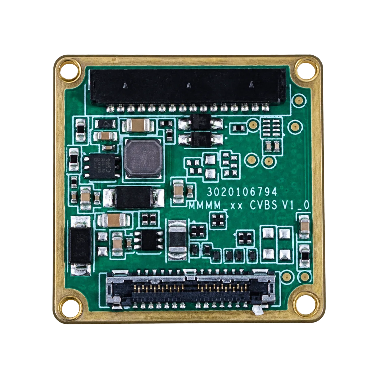
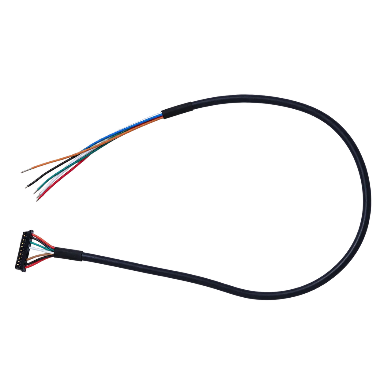

Use the matching 16-pin signal table and complete AeroMini datasheet for the illustrated connector layout and 26-pin MIPI/DVP reference. Do not connect 12 V to POWER_IN1 or POWER_IN2 or infer wire functions from cable colors. The Type-C kit requires its own matched wiring guide.
CAMCUDA SuperMini 640 Ultra-Light LWIR Thermal Camera Module
Compact-Core 640×512 Imaging Comparison for Space-Constrained OEM Systems
The SuperMini 640 (imaging SKU: CC-SM640-I50) is a 640×512 uncooled VOx core with an 8 µm pixel pitch and NETD ≤40 mK at 25°C, F/1.0. It is the compact-core comparison for projects that can support its power rails and host interface. SuperMini 640 imaging operates at 50 Hz and does not measure temperature; SuperMini 640T is the separate 30 Hz thermographic model, with different output data and measurement requirements.
Typical core consumption is ≤0.5 W at 25°C, excluding the expansion board. Core dimensions are 13 mm × 13 mm × 13.4 mm and weight is under 3.5 grams, excluding lens, flange and user expansion board. The imaging core operates from -40°C to +70°C. Choose the lens, connector clearance and output mode before enclosure design; the published core figures are not a complete installed camera specification.
Comprehensive Technical Specifications
| Subsystem | Parameter | Specification Details |
|---|---|---|
| Detector Core | Product Model / Imaging SKU | SuperMini 640 / SKU: CC-SM640-I50 |
| Detector Class | VOx uncooled LWIR thermal imaging core | |
| Native Resolution | 640 × 512 pixels | |
| Detector Pixel Pitch | 8 µm | |
| Spectral Range | 8 to 14 µm (LWIR) | |
| Maximum Frame Rate | 50 Hz imaging; separate SuperMini 640T thermographic model: 30 Hz. Confirm the selected output mode. | |
| Optics & FOV | Field of View (FOV) | Lens-dependent. For example, 3.7 mm: 90.0° H × 68.2° V; 11 mm: 24.9° H × 20.0° V. Confirm the selected lens. |
| Optical Configuration | 3.7 / 6.1 / 8.7 / 11 mm F1.0 athermal lens options; complete assembly size and mass vary. | |
| Lens Construction | Confirm specific lens material & drawings during RFQ | |
| Electrical & Host I/O | Supply Voltage | MAIN_POWER 3.8–5.2 V plus separate regulated 3.3 V and 1.8 V rails. Confirm rail noise limits and power-on timing. |
| Power Consumption | ≤0.5 W typical core consumption @ 25°C, excluding expansion board. | |
| Primary Host Interface | 8-bit LVCMOS / BT656 or 2-lane MIPI; BT656 and MIPI cannot operate simultaneously. UART control uses 1.8 V logic. CVBS requires an external video-buffer IC. | |
| Physical Connector | Hirose DF40C-30DP-0.4V(51) 30-pin core connector; follow the selected assembly’s pinout and mating orientation. | |
| Calibration & Env. | Imaging / Thermography Boundary | SuperMini 640 is imaging-only. Temperature measurement and temperature-data specifications apply only to the separate SuperMini 640T. |
| Operating Temperature | -40°C to +70°C for imaging; thermographic operating conditions must be checked separately. | |
| USB Evaluation Option | Optional TMS6102V100F022 4-pin USB expansion board; confirm supplied items, host software and output format during RFQ. |
Key Engineering & RFQ Integration Notes
- 📌 Target Application Fit: Compact drones, micro-gimbals and space-constrained embedded thermal imaging where the host can support the core’s rail and interface requirements.
- 📌 Host Hardware Compatibility: Validate the selected digital receiver, 1.8 V UART levels, all required power rails, cable and expansion board. A compact core is not a guarantee of direct SPI or plug-and-play USB compatibility.
- 📌 RFQ Support Checklist: Specify imaging or thermography, lens/FOV, host interface, expansion-board needs, complete mechanical envelope, sample quantity and estimated annual volume. Compare total integration costs, not core size alone.
For this SuperMini core configuration, review the complete manual’s 30-pin orientation and pin table, PDF pages 6–7 and bare-core mechanical drawing, PDF page 13. Both references exclude the optional expansion board; the mechanical drawing also excludes the lens. Confirm the drawing and wiring guide for the supplied assembly.
If you’re looking for turnkey, fully housed thermal devices built for rugged field use, check out the full line of field observation devices.
6. Optics, Materials, and Radiometry: Managing Bill-of-Materials (BOM) Costs
In visible cameras, lenses are stamped out of BK7 glass or acrylic for pocket change. In the LWIR band (8–14 µm), standard glass is as opaque as a sheet of plywood. Thermal optics require specialized infrared-transmissive substrates that easily eat up 30% to 50% of your total hardware BOM if you don’t design carefully.
Monocrystalline Germanium (Ge)
Germanium has long been the standard for high-end thermal glass. It brings a massive refractive index (n ≈ 4.0 at 10 µm), which allows optical designers to create fast apertures, compact profiles, and minimal aberrations using fewer elements. It is also physically tough. But Germanium is expensive, rare, and has to be turned on single-point diamond turning (SPDT) lathes. Worse, it has a high thermal coefficient of refractive index (dn/dT = 396 × 10-6 / K). That means when the temperature shifts, the focal plane drifts badly unless you spend extra money on mechanical or motorized athermalization mechanisms.
Chalcogenide Glass (GASIR, Ge-Se-Te alloys)
To drop optical costs in high-volume OEM builds, optical engineers rely on Chalcogenide amorphous glass. These alloys can be heated and stamped using Precision Glass Molding (PGM), churning out finished aspheric and diffractive elements in seconds without diamond turning. That cuts lens manufacturing costs by up to 60%. Even better, Chalcogenide has a much lower dn/dT (around ~35 × 10-6 / K), providing natural passive optical athermalization across -40°C to +85°C without moving parts.
Wafer-Level Etched Silicon Optics
For compact, entry-level module designs, wafer-level etched Silicon optics are one cost consideration. Do not assume that the AeroMini or SuperMini lenses use this construction; confirm the optical material and assembly drawing for the selected configuration. While raw Silicon exhibits minor absorption dips across the 8–14 µm band compared to Germanium, multi-layer anti-reflective (AR) coatings keep transmission high enough for short-to-medium range industrial monitoring.
7. OEM Sourcing and Implementation Checklist
Before locking in your BOM or signing off on an RFQ for your thermal cores, run your system requirements through this practical integration checklist:
- ⚙️ 1. Modality Validation: Double-check that your application truly requires passive emissive thermal detection (8–14 µm) rather than cheap reflected NIR (0.85–0.94 µm).
- ⚙️ 2. Resolution & Target Pixel Coverage: First assess whether lower-resolution sensing (for example, 160×120) is sufficient or whether 640×512 imaging is required. Use the thermal imaging calculator to estimate FOV and target pixel coverage for the selected resolution, pixel pitch, lens, target size and distance. Its pixel-based planning assumptions are not resolved line-pair guarantees or guarantees of detection, recognition, identification or temperature-measurement performance:
- 👉 Geometry: Record the target’s critical dimension, working distance and required scene coverage.
- 👉 Optical choice: Check target pixels for the actual sensor and lens; equal focal lengths do not imply equal FOV across different pixel pitches.
- 👉 Validation: Test representative scenes, contrast, motion and weather on the configured system before accepting an operational range.
- ⚙️ 3. Interface Matching: Match the actual model, board, video format, control levels and host receiver. AeroMini interfaces are board-dependent; SuperMini requires its core interface or optional expansion board. Do not infer SPI, UVC or V4L2 compatibility from connector names.
- ⚙️ 4. Thermal Sensitivity (NETD): Review AeroMini 640 at ≤30 mK and SuperMini 640 at ≤40 mK, both specified at 25°C, F/1.0, then test the required scene contrast. NETD is not temperature-measurement accuracy; neither imaging-only model measures temperature.
- ⚙️ 5. Processing Offload: Confirm the module’s documented correction controls, output format and host-side processing requirements for the selected firmware. Benchmark latency and CPU load; do not assume an onboard hardware NUC/DSP architecture or a particular bit depth without configuration-specific evidence.
- ⚙️ 6. Shock & Thermal Envelopes: Check the selected assembly against the environment: AeroMini imaging is specified at -40°C to +80°C and SuperMini imaging at -40°C to +70°C. Request configuration-specific shock/vibration evidence and complete assembly drawings; thermographic operating conditions need separate review.
8. Deep-Dive Frequently Asked Questions (FAQ)
What is the difference between a cheap converted IR camera and a true LWIR thermal camera?
Can low-cost thermopile arrays replace microbolometer cores in embedded designs?
Why do cheap consumer thermal dongles fail in industrial OEM and drone projects?
How do optical materials affect the total bill-of-materials (BOM) cost of an entry-level LWIR camera?
What are the latency and processing bottlenecks when deploying low-cost thermal cores to edge AI processors?
📚 References & Further Reading
- Industry Standard: Accelerating edge vision compute graphs with the Khronos OpenVX Vision Acceleration Standard
- Industry Standard: Hardware neural network acceleration using Qualcomm AI Embedded Solutions
- Related Guide: Engineering considerations for Outdoor Field Thermal Imaging Systems
- Related Guide: Sourcing industrial-grade Field Observation & Optical Devices
- Related Guide: Overview of multi-spectral Industrial & Commercial Thermal Applications