Drone thermal vision: the inspection plan starts before the aircraft leaves the case
Application workflow for UAV inspection teams
Drone thermal vision: the inspection plan starts before the aircraft leaves the case
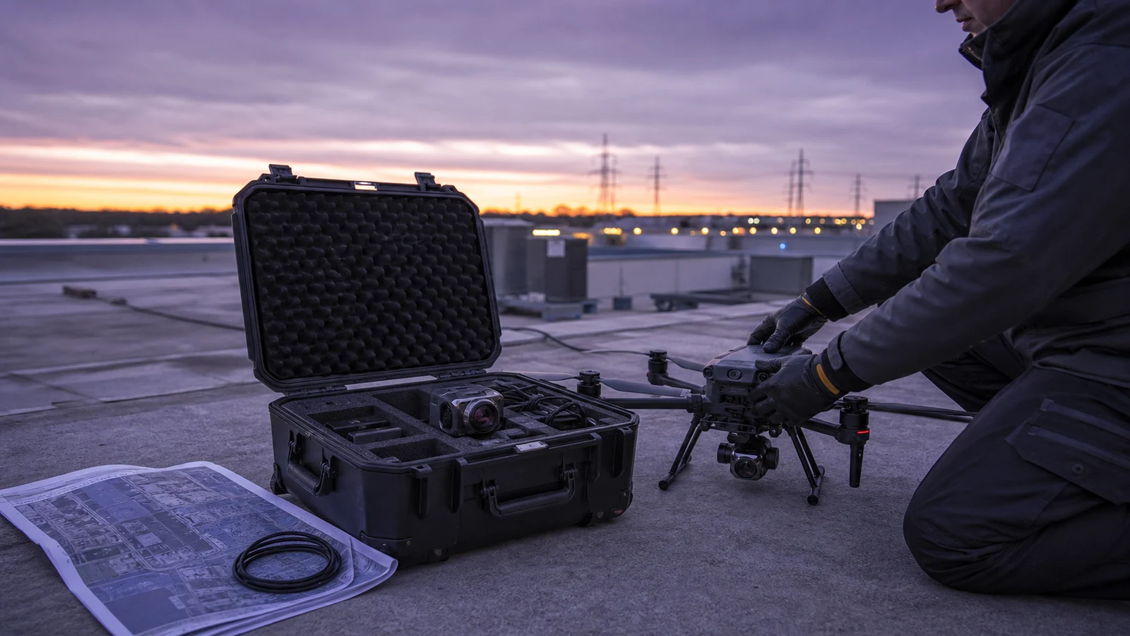
Consider an illustrative preflight scene at 5:40 a.m.: the aircraft is assembled beside a commercial roof. Batteries are warm, the airspace check is complete, and the operator has a clean thermal feed. Then the facilities manager asks the question nobody wrote down: what exactly would count as useful evidence?
That is the real starting point for drone thermal vision. A payload can produce an attractive image and still fail the inspection if the team has not defined the target, thermal window, viewing geometry, recorded evidence, and follow-up action before launch.
Quick answer
Build a drone thermal vision mission backward from the decision the inspection must support. Define the target condition, minimum useful target detail, expected thermal contrast, flight window, operator view, saved evidence, and ground-verification step. Only then compare module resolution, lens/FOV, weight, power, interfaces, and procurement documents. A current reference is the Featured CAMCUDA AeroMini 640, selected here as the non-radiometric 9 mm model with USB + CVBS + MIPI. It provides thermal imagery without calibrated temperature measurement and remains one part of that complete evidence chain.
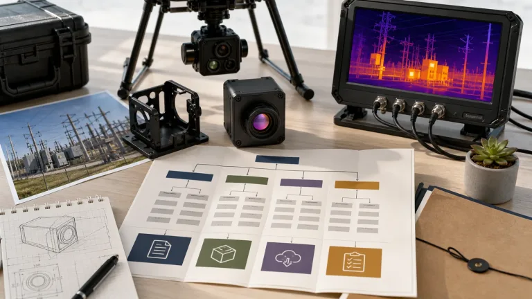
Drone thermal vision mission chart: start with the decision
The fastest way to overbuy or mis-specify a payload is to begin with a resolution number. Start with the inspection decision instead.
| Inspection decision | Evidence the team needs | Payload question | Field constraint to record |
|---|---|---|---|
| Which roof zones need ground verification? | Repeatable thermal pattern tied to a mapped roof area | Does the lens/FOV preserve enough target detail at the planned altitude? | Time window, wind, surface condition, route overlap, and asset map |
| Which electrical asset deserves closer inspection? | Comparable views of similar components under similar load | Can the operator hold a consistent angle and working distance? | Load state, reflections, line of sight, safety perimeter, and asset ID |
| Where should a field technician investigate next? | Image or clip with location, orientation, and a clear handoff note | How will the thermal stream be viewed, recorded, and exported? | Operator display, onboard capture, file naming, and ground access |
| Can the workflow be repeated next month? | Documented route and capture conditions, not just a striking frame | Can the same module and integration path produce consistent evidence? | Altitude, speed, angle, palette/settings, weather, and inspection window |
This is also the difference between a camera demonstration and an inspection system. NVIDIA’s physical AI and Jetson discussion connects sensing, processing, and action in real-world systems. Micron’s Smart Sight manufacturing example describes using AI to identify and analyze defects in semiconductor production. These are workflow examples, not evidence of CAMCUDA module performance or host compatibility. For a CAMCUDA buyer, the useful lesson is to begin the payload specification with the decision the thermal evidence must support.
Define a useful thermal observation before choosing hardware
A thermal camera records infrared radiation, but the resulting pattern still depends on the target, surface properties, environment, distance, optics, and viewing angle. FLIR’s emissivity explainer shows why surface emissivity and reflected radiation affect interpretation. A reflective metal component and a coated housing can look different for reasons that have little to do with the fault the team hopes to find. The selected non-radiometric AeroMini provides imagery; a requirement for calibrated temperature readings needs a separately specified and validated radiometric configuration.
So write one sentence before choosing the module:
We need to distinguish this target condition from its comparison condition, at this working distance, during this operating window, and save enough context for this follow-up decision.
That sentence forces useful conversations. If the target is a broad roof zone, coverage may dominate. If the target is a small connector among similar components, target pixels and pointing stability become more important. If the mission is a night perimeter sweep, the output path and operator workload may outweigh radiometric analysis.
The practical trade-off is field of view. A wider lens covers more area per pass, but a small target occupies fewer pixels at the same distance. A narrower view places more pixels on the target, but increases passes, pointing demands, and the chance that the operator loses context. There is no universal winner. Use CAMCUDA’s Thermal Imaging Calculator to compare scene coverage and target sampling for the planned lens and working distance. Its geometry and DRI estimates are planning aids, not a guarantee of detection, recognition, or inspection success. The right answer still comes from target size, aircraft behavior, field conditions, and the evidence requirement.
CAMCUDA’s live drone thermal camera application page helps define the aircraft, payload, and operating context. If the aerial finding will be checked by a technician or converted into a fixed monitoring task, the outdoor and field thermal imaging application page helps define that second stage.
Where the AeroMini 640 fits a drone thermal vision build
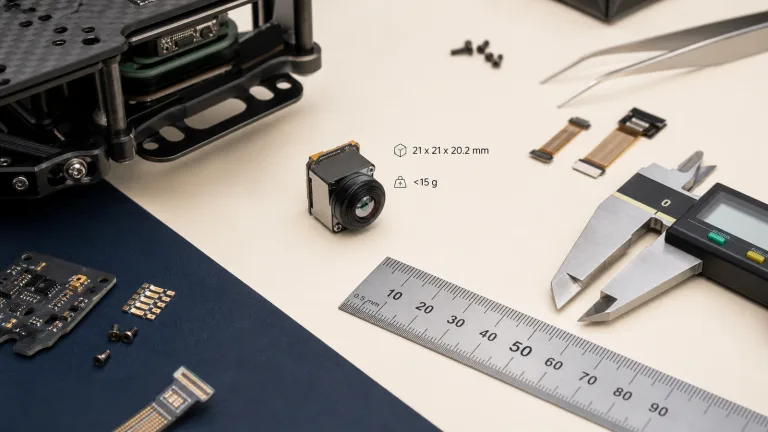
The CAMCUDA AeroMini 640 is a current Featured product. The reference here is its non-radiometric 9 mm configuration with the USB + CVBS + MIPI package. It is a module for OEM and payload integration, so the team still defines the enclosure, host electronics, display, recording path, mount, and aircraft integration. Published module dimensions, mass, and typical power do not describe a complete ready-to-fly payload.
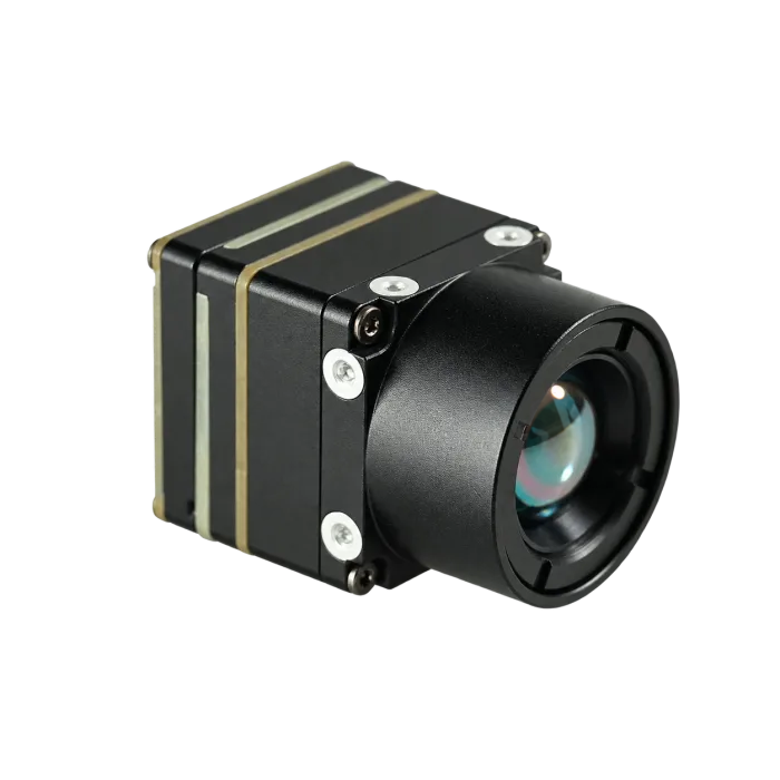
| Model | AeroMini 640, non-radiometric, 9 mm, USB + CVBS + MIPI |
|---|---|
| Detector | Vanadium oxide uncooled infrared focal plane detector |
| Resolution | 640 × 512 |
| Pixel pitch | 12 μm |
| Non-radiometric factory frame rate | 60 Hz factory default; optional 30 Hz factory configuration. Confirm the delivered rate for each output and host. |
| Spectral range | 8–14 μm |
| NETD | ≤30 mK at 25°C, F/1.0 |
| Supply voltage | Illustrated POWER_IN1 and POWER_IN2 pins: 5 V only. Confirm the selected board’s complete power requirements before wiring. |
| Typical power consumption | <0.5 W typical module consumption at 25°C; complete-kit consumption may differ |
| Digital video | USB and MIPI paths in the selected package; confirm format, firmware, host support, and simultaneous-output limits |
| Communication | 16-pin board: RS232_RX/TX at pins 3/4; signal levels are not specified in that pin table. Separate 26-pin interface: UART0 TX/RX at pins 19/20, both 3.3 V. |
| Analog video | CVBS in the selected package; confirm PAL/NTSC mode, board revision, and delivered output rate |
| Dimensions | 21 × 21 × 28 mm, excluding lens and flange; request the complete 9 mm assembly drawing |
| Weight | <20 g, excluding lens and flange; this does not establish compliance with a below-15 g design target |
| Operating temperature | −40°C to +80°C |
For a compact drone thermal vision payload, the published AeroMini figures are <20 g and 21 × 21 × 28 mm excluding the lens and flange, with typical module consumption below 0.5 W at 25°C. Those figures do not establish that a below-15 g core requirement will be met. Keep that requirement visible in the RFQ, request the mass of the exact ordered assembly, and measure complete-system power. The carrier electronics, lens, enclosure, gimbal or fixed mount, wiring, and vibration strategy still count against the aircraft’s size, weight, and power budget.
The 640 × 512 detector also does not answer the range question by itself. The lens/FOV and target geometry decide how many pixels land on the feature that matters. Procurement should therefore send target size, expected distance, and desired scene width with the RFQ instead of asking whether “640 is enough” in the abstract. Teams comparing related form factors can also review CAMCUDA’s thermal imaging cores category.
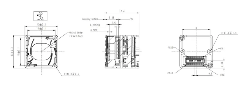
If the core mass or envelope is the limiting requirement, assess the Featured SuperMini 640 imaging-only model at 50 Hz as a separate design route. Its published bare core is 13 × 13 × 13.4 mm and <3.5 g, excluding the lens, flange, and user expansion board. The drawing below comes from Figure 4.1 on physical page 13 of the SuperMini V1.0.0 product manual. It does not establish the size or mass of an AeroMini assembly, and the complete SuperMini payload still needs its own budget and interface design.
A pre-dawn inspection where the useful window is closing
In this illustrative scenario, an OEM team is preparing a compact payload for roof and utility-site surveys. The aircraft has a limited 5 V payload rail. The thermal core target is below 15 g because the enclosure, mount, and wiring still need margin. AeroMini’s published <20 g figure, excluding lens and flange, does not guarantee that target; the team must review an exact assembly or consider a different core. The operator has one live display, while the engineering team needs recorded evidence that can be tied to an asset map after landing.
The crew arrives before sunrise because the thermal pattern they want may become harder to distinguish as solar loading changes the surface. The aircraft is safe to fly, but the mission still needs its own acceptance test:
- Identify the comparison area before launch.
- Choose a route and altitude that keep the smallest useful target large enough in frame.
- Record the surface condition, weather, and time window.
- Capture visible context or an asset reference so a technician can find the same location.
- Define whether a suspected anomaly triggers a second pass, ground inspection, or later fixed monitoring.
The realistic mistake is chasing the most dramatic palette. A high-contrast frame may be visually persuasive, but it can hide whether the target is repeatable, correctly located, or comparable with neighboring assets. The crew needs evidence that survives the morning briefing, not merely a screenshot that looks hot.
FLIR’s 2017 aerial thermography case using the T640bx is a historical example of reaching roofs, photovoltaic systems, buildings, and power lines with an airborne camera. Its equipment and results do not describe the selected CAMCUDA module. The transferable lesson is to protect access to the asset and collect useful inspection context, then validate the current payload against the intended task.
The evidence path is part of drone thermal vision
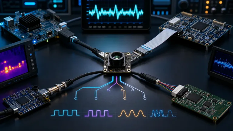
A mission sheet should name where the image goes while the aircraft is flying and what is saved after landing. In the selected AeroMini USB + CVBS + MIPI package, USB can support host capture and development, while CVBS may serve an analog monitor, recorder, or transmitter. Specify the required PAL/NTSC mode and confirm output rate, host support, and which outputs can run together. Video and serial control are separate design questions; USB video does not by itself establish a USB serial port.
Do not ask for every interface “just in case.” That usually obscures the actual architecture. State the operator display, onboard computer, recording destination, control path, connector constraints, and acceptable conversion stages. A direct path may reduce integration complexity; a more flexible path may better support analytics or evidence storage. The trade-off belongs in the system diagram.
The same discipline applies to flight operations. For US operations under Part 107, FAA AC 107-2A explains preflight assessment, aircraft condition, crew responsibilities, and control-link checks. The advisory circular is guidance for the applicable operating rules, not a thermal-imaging specification. Use it for aircraft safety planning, then add a separate thermal mission acceptance sheet for target and evidence quality.
For North America procurement, security monitoring, utility inspection, or industrial programs, list documentation needs before ordering. Request the configuration-matched specification, interface reference, and complete-assembly drawing; ask which NDAA-related statements and CE/RoHS documents can be supplied for the configuration, destination, and intended use. Have the buyer’s procurement and legal teams assess the documents against the actual program requirements. A product page or requested statement does not establish eligibility or certify an assembled aircraft.

For the separate 26-pin MIPI/DVP interface, UART0 TX is pin 19 and RX is pin 20, both 3.3 V; POWER_IN2 pins 12, 25, and 26 are 5 V inputs. Do not apply those UART levels to the 16-pin RS232 connection. Use the current AeroMini datasheet, matched interface reference, product FAQ, and official SDK and developer-resource directory to identify the required board, firmware, commands, and host package before implementation. Resource availability alone does not establish software compatibility; test the exact capture and control path on the intended host.
Five mistakes that weaken a thermal inspection before takeoff
- Buying resolution before defining target geometry. Resolution matters, but lens/FOV, distance, angle, and target size decide the useful detail.
- Ignoring the thermal window. Weather, solar loading, surface condition, equipment state, and atmospheric effects can change what the camera sees.
- Using palette drama as an acceptance criterion. A strong-looking image is not automatically a repeatable or correctly interpreted result.
- Separating the live view from the evidence plan. The operator may see enough to fly while the saved record lacks location or comparison context.
- Leaving ground follow-up undefined. An anomaly without an asset ID, map reference, or next action becomes an interesting image instead of a maintenance input.
One-page RFQ mission sheet for drone thermal vision
Send this information with the first inquiry. It gives engineering and procurement a common starting point and reduces the temptation to substitute generic specifications for mission requirements.
| Mission | Asset type, inspection decision, and who uses the result |
|---|---|
| Target | Smallest important feature, expected contrast, comparison condition, and surface type; state separately if calibrated temperature readings are required |
| Geometry | Working distance or altitude, desired scene width, view angle, route, and stabilization limits |
| Environment | Time window, ambient conditions, wind, precipitation limits, equipment load state, and access constraints |
| Payload limits | Mass target, complete assembly envelope, power rail, mounting, enclosure, cable routing, and vibration expectations; retain any below-15 g requirement explicitly |
| Data path | Operator display, recording destination, host board, selected USB/CVBS/MIPI mode and rate, and board-specific control pins and signal levels |
| Evidence | Still image or video, asset/location context, naming, repeat-pass rule, and post-flight review owner |
| Documents | Current datasheet, complete-assembly drawing, matched interface and firmware references; ask which NDAA-related and CE/RoHS documents can be supplied for buyer review |
Use CAMCUDA’s support downloads and support FAQ while preparing the sheet. Then send the completed mission context through the contact and RFQ page.
Drone thermal vision FAQ
What does drone thermal vision mean for an OEM buyer?
It means more than mounting a thermal sensor on an aircraft. The buyer is defining a system that must place useful thermal detail on an operator display or recording path, within aircraft limits, under field conditions that support the intended inspection decision.
Why define the target before choosing resolution?
Because the useful question is how many pixels cover the smallest important target at the planned distance and field of view. Detector resolution is only one input to that geometry.
Does a wider field of view make drone inspection easier?
It improves area coverage and context, but small targets occupy fewer pixels at the same distance. A narrower field can preserve more target detail while requiring more passes and tighter pointing. Choose against the mission, not a general preference.
Does a colorful thermal image prove that the team found a fault?
No. Palette and level/span choices can make patterns easier to see, but interpretation still depends on surface properties, reflections, environment, comparison conditions, and the inspection method. Treat the image as evidence that needs context. The selected non-radiometric AeroMini provides imagery, not calibrated temperature readings.
When is USB useful in a drone thermal vision payload?
USB is useful for host capture, software development, and integrations where an onboard computer or nearby evaluation host owns the stream. For the selected AeroMini package, confirm the host, format, delivered rate, power, connectors, and separate operator-view requirement. Check serial control independently; USB video does not establish a USB serial port.
When should a buyer ask about CVBS analog output?
Discuss it when the payload uses an analog transmitter, display, recorder, or retrofit video chain. The AeroMini USB + CVBS + MIPI package includes a CVBS path; specify PAL/NTSC needs and confirm the selected board, delivered rate, and permitted simultaneous outputs. A different interface package needs its own matched guide.
What should be saved with a thermal image?
At minimum, preserve the asset or location reference, time, route or viewpoint, relevant environmental and operating conditions, and the reason the frame was captured. The exact evidence package depends on the inspection method and customer procedure.
What should North America procurement request?
Request the exact product specification, complete-assembly drawing, interface and firmware references, configuration list, and sourcing documents required by the program. Ask which NDAA-related statements and CE/RoHS documents can be supplied for the selected configuration and destination. The buyer’s procurement and legal teams should review their scope; a requested statement alone does not establish program eligibility or complete-aircraft compliance.
Send the mission, not just the resolution
If your team is building drone thermal vision into an inspection platform, review the AeroMini 640 product page and the drone application path. Then send CAMCUDA the target, working distance, scene width, exact mass limit, evidence path, and documentation needs. Compare the separate SuperMini route if core size is the constraint. Use the sample review to agree the lens, board, firmware, and tested capture mode before the first inspection flight.
Technical author: Daniel · Hardware Support; Sales contributors: Vivian, Lena and Sophie.