OEM Camera for Drone Integration: 640 Thermal & EO Vision Modules
OEM Camera for Drone Integration: 640 Thermal & EO Vision Modules
Modern unmanned aerial vehicle (UAV) payload engineering is a brutal balancing act. You are constantly juggling thermal sensitivity, optical sharpness, harsh power envelopes, and edge processing throughput. As mission profiles shift away from basic aerial videography toward sub-millimeter thermographic utility inspections, standoff search and rescue (SAR), and real-time autonomous target tracking, standard consumer payloads hit a hard wall. Integrating an OEM camera for drone platforms demands micro-sized uncooled long-wave infrared (LWIR) cores, high-definition electro-optical (EO) sensors, and deterministic low-latency digital video interfaces built specifically to survive strict Size, Weight, Power, and Cost (SWaP-C) limitations.
Here’s the deal: system architects face ruthless mechanical, electrical, and radiometric hurdles when designing custom multi-sensor gimbals. Selecting the optimal combination of sensor pitch (such as 12 μm VOx detectors), optical focal length, thermal sensitivity (NETD ≤ 40–50 mK), and onboard Neural Processing Units (NPUs running up to 6 TOPS) determines whether an airframe can isolate micro-anomalies on utility grids or track moving vehicles through tree cover. This engineering blueprint breaks down the architectural trade-offs, bench-tested integration workflows, interface protocols, and real-world hardware profiles of market-leading OEM thermal and dual-sensor vision modules.
Table of Contents
- 👉 1. EO & LWIR Thermal Architecture for Drone Payloads
- 👉 2. SWaP-C Optimization & Gimbal Mechanical Interfacing
- 👉 3. Edge AI, Sensor Fusion, and Machine Vision Integration
- 👉 4. OEM Hardware Specifications: AeroMini 640 & AI VisionCube
- 👉 5. Digital Video Interfaces & Radiometric Calibration Workflows
- 👉 6. Industrial Drone Application Benchmarks
- 👉 7. Technical Integration FAQ
1. EO & LWIR Thermal Architecture for Drone Payloads
Core Sensor Physics: Uncooled VOx vs. Visible CMOS
Integrating a multi-spectral imaging payload begins down at the raw detector physics. For thermal sensing, Vanadium Oxide (VOx) uncooled microbolometers operating across the Long-Wave Infrared (LWIR) band (8 to 14 μm) represent the industry standard. Look, cooled Indium Antimonide (InSb) or Mercury Cadmium Telluride (MCT) sensors might offer extreme sensitivity, but their bulky cryogenic Stirling coolers demand massive amounts of power and add dead weight—making them a complete non-starter for sub-2 kg commercial UAVs. Uncooled VOx cores, on the other hand, give you instantaneous operational readiness, run cool on less than 0.5 W of power, and deliver crisp 640 × 512 native thermal resolution at a tight 12 μm pixel pitch.
Thermal sensitivity is quantified by Noise Equivalent Temperature Difference (NETD). An NETD rating of ≤50 mK (with precision factory-binned options down to ≤40 mK at 25 °C, F/1.0) guarantees that subtle temperature deltas across high-voltage transmission lines, solar cells, or concrete bridges stand out cleanly above the electronic noise floor. Inside an uncooled microbolometer, incoming infrared photons warm up the suspended VOx pixel bridge, changing its electrical resistance. A high-speed Read-Out Integrated Circuit (ROIC) samples this resistance, converting it into a 14-bit digital stream before applying real-time Non-Uniformity Correction (NUC).
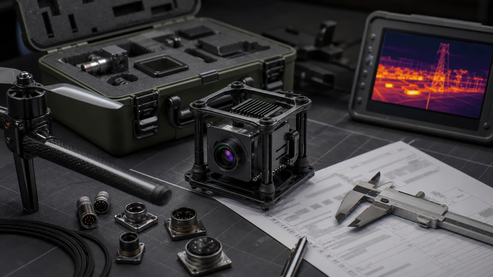
When you pair this LWIR setup with a high-performance visible CMOS sensor (such as a 1/2.8-inch or 1/2.6-inch rolling or global shutter imager running in the 400 to 700 nm visible spectrum), you solve the biggest issue with thermal imagery: lack of contextual spatial detail. Visible cameras provide the fine spatial contrast, sharp text reading, and color classification that pilots need during daytime runs. Proven integration models from industry veterans like Workswell demonstrate that co-axial optical alignment between EO and IR channels is mandatory if you want repeatable, multi-spectral utility mapping and tactical tracking.
Optical Selection & Field of View (FOV) Calculations
In the shop, calculating your optical setup comes down to your operating ceiling, cruising airspeed, target dimensions, and required Ground Sample Distance (GSD). GSD defines the physical distance on the ground covered by a single detector pixel:
GSDthermal = (Pixel Pitch × Operating Altitude) / Focal Length
Let’s run the actual math: flying a 640 × 512 thermal core (12 μm pitch) at an altitude of 50 meters with a 9 mm focal length gives you:
GSD = (0.012 mm × 50,000 mm) / 9 mm = 66.67 mm/pixel (6.67 cm/pixel)
Swap that out for a 25 mm telephoto lens at that same 50-meter deck, and your GSD drops to 2.40 cm/pixel. That gives you nearly three times the spatial detail on critical hardware like utility bushings, insulators, and transformer linkages. But remember the trade-off: longer glass drastically narrows your Field of View (FOV). That means your gimbal stabilization loops have to be locked down tight to stop rotational blur from ruining your raw frames.
| Lens Focal Length | Horizontal × Vertical FOV | Spatial Resolution (IFOV) | Target Operational Profile |
|---|---|---|---|
| 4 mm | 100° × 82° | 3.00 mrad | Close-quarters situational awareness, indoor navigation, wide mapping |
| 7 mm | 64° × 52° | 1.71 mrad | Wide-area crop health mapping, low-altitude terrain inspection |
| 9 mm | 48.7° × 38.6° | 1.33 mrad | Standard industrial survey, solar PV thermography (IEC 62446-3) |
| 13 mm | 31.9° × 25.7° | 0.92 mrad | Substation electrical inspection, mid-range search and rescue |
| 18 mm | 24.2° × 19.5° | 0.67 mrad | High-voltage line surveys, structural perimeter security |
| 25 mm | 17.5° × 14.0° | 0.48 mrad | Long-range target detection, structural wind turbine blade audits |
| 35 mm | 12.5° × 10.0° | 0.34 mrad | High-altitude tactical standoff, border reconnaissance |
| 50 mm | 8.8° × 7.0° | 0.24 mrad | Persistent aerial tracking, ultra-long-range surveillance |
For detailed bench integration guidelines and mechanical assembly tips, check out our engineering walkthrough on drone with thermal imaging OEM payload core integration.
2. SWaP-C Optimization & Gimbal Mechanical Interfacing
Mechanical Packaging and Dynamic Mass Budgets
Every single gram inside a direct-drive brushless UAV gimbal matters. Extra weight cranks up the holding torque requirements on your pitch and roll motors, pulls more continuous current from your flight packs, and shifts your payload center of gravity (CG). The bare CAMCUDA AeroMini 640 core weighs under 20 grams and measures just 21 × 21 × 28 mm without a lens. That minimal footprint keeps rotational inertia low enough to drop straight into ultra-compact 2-axis or 3-axis brushless gimbals without cooking your motor drivers.
When you mount a camera for drone operations, mechanical rigidity is everything. Fasten the core securely via its front or rear M2 threaded points to stamp out micro-vibrations caused by motor poles and propeller blade passage frequency (BPF). If those high-frequency vibrations make it to the VOx focal plane array, you will see high-frequency jitter and rolling-shutter tearing on the video stream. We recommend CNC-machined 6061-T6 aluminum or magnesium mounts combined with silicone-damped isolation bobbins tuned to absorb the resonance profile of your airframe.
Thermal dissipation is another beast altogether. You don’t have the luxury of active cooling fans on a compact micro-payload due to weight and acoustic penalties. Heat generated by the processing backend must conduct directly away from the VOx detector assembly through the aluminum housing into the gimbal yoke. When you operate across industrial temperature extremes (-40 °C to +80 °C), you need a reliable mechanical NUC shutter or rock-solid shutterless temperature compensation algorithms to prevent thermal drift from washing out your imagery during long flights.
Power Rail Architecture and Electrical Noise Isolation
Microbolometer sensors are extremely sensitive to dirty electrical rails. High-power brushless Electronic Speed Controllers (ESCs) and onboard 5.8 GHz video transmitters throw substantial high-frequency switching hash back onto the DC bus. If that noise reaches the analog-to-digital converter (ADC) in the ROIC, you will see noticeable horizontal banding across your 14-bit thermal image.
OEM cores like the AeroMini 640 run on configurable 5 V or 12 V DC rails, pulling less than 0.5 W under steady-state operation at 25 °C. To keep your power delivery clean when running off main flight packs (4S to 12S LiPo):
- ⚙️ Synchronous Buck Regulation: Drop flight battery voltage down to an intermediate 5.0 V or 12.0 V rail using an efficient DC-DC buck converter switching well above 1.5 MHz (far outside the sensor sampling bandwidth).
- ⚙️ Ultra-Low-Noise LDO Filtering: Follow your switching stage with a high-PSRR (Power Supply Rejection Ratio) Low-Dropout regulator to crush ripple down under 10 mV peak-to-peak.
- ⚙️ Dedicated Ground Isolation: Keep high-speed digital return paths cleanly separated from noisy ESC motor returns to eliminate ground loops that trash BT.656 and USB data signals.
- ⚙️ RF Shielding: Enclose all flexible flat cables (FFC) carrying digital video in grounded copper or aluminum foil tape so emitted EMI doesn’t blind your onboard GNSS receiver.
3. Edge AI, Sensor Fusion, and Machine Vision Integration
Modern aerial missions have moved way past having an operator stare at raw video on a ground station monitor. Instead of burning up RF bandwidth streaming uncompressed high-bitrate video down to a ground station, the smart approach is running edge compute right behind the optics. This setup parses pixels locally and outputs real-time target bounding boxes, classifications, and telemetry vectors directly aboard the aircraft.
Leveraging proven Machine Vision frameworks enables true multi-sensor fusion. By aligning a 1080p visible sensor at 30 Hz with a 640 × 512 LWIR core running at 50/60 Hz, an onboard edge processor carries out real-time spatial registration. Overlaying crisp visible edges onto false-color thermal palettes allows an operator to read equipment placards and spot fine structural cables while instantly identifying overheating electrical contacts.
The CAMCUDA AI VisionCube series implements this architecture by placing hardware Neural Processing Units (NPUs) directly into the sensor package:
- ✅ 1 TOPS Processing Architecture (S / ST Series): Tailored for single-sensor AI tasks, running lightweight CNN models (like YOLOv5-Nano or MobileNet-SSD) at a solid 30 fps. Perfect for real-time person, vehicle, and livestock detection during SAR or wildlife monitoring missions.
- ✅ 6 TOPS Processing Architecture (D / DT Pro Series): Built for dual-visible (wide-angle + telephoto) and multi-spectral EO/IR pipelines. This multi-core engine runs concurrent deep neural networks across both optical streams, supporting persistent object re-identification (ReID), occlusion-resistant tracking, and automated optical zoom handoffs.
Target tracking coordinates and bounding offsets feed straight to an autopilot running ArduPilot or PX4 over high-speed UART, RS232, or RS422. The autopilot translates target offsets into standard MAVLink messages (such as COMMAND_INT or VISION_POSITION_ESTIMATE), completing the hardware tracking loop to keep dynamic targets dead-center in the frame without pilot intervention.
For more details on evaluating micro-thermal cores, take a look at our hands-on teardown in the Thermal Master P1 review, technical specs, limitations, and OEM integration guide.
4. OEM Hardware Specifications: AeroMini 640 & AI VisionCube
Selecting the right OEM camera for drone payload integration requires analyzing detector physics, lens configurations, edge compute power, and physical dimensions. Below are detailed technical profiles and a consolidated engineering matrix for CAMCUDA’s specialized UAV imaging modules.
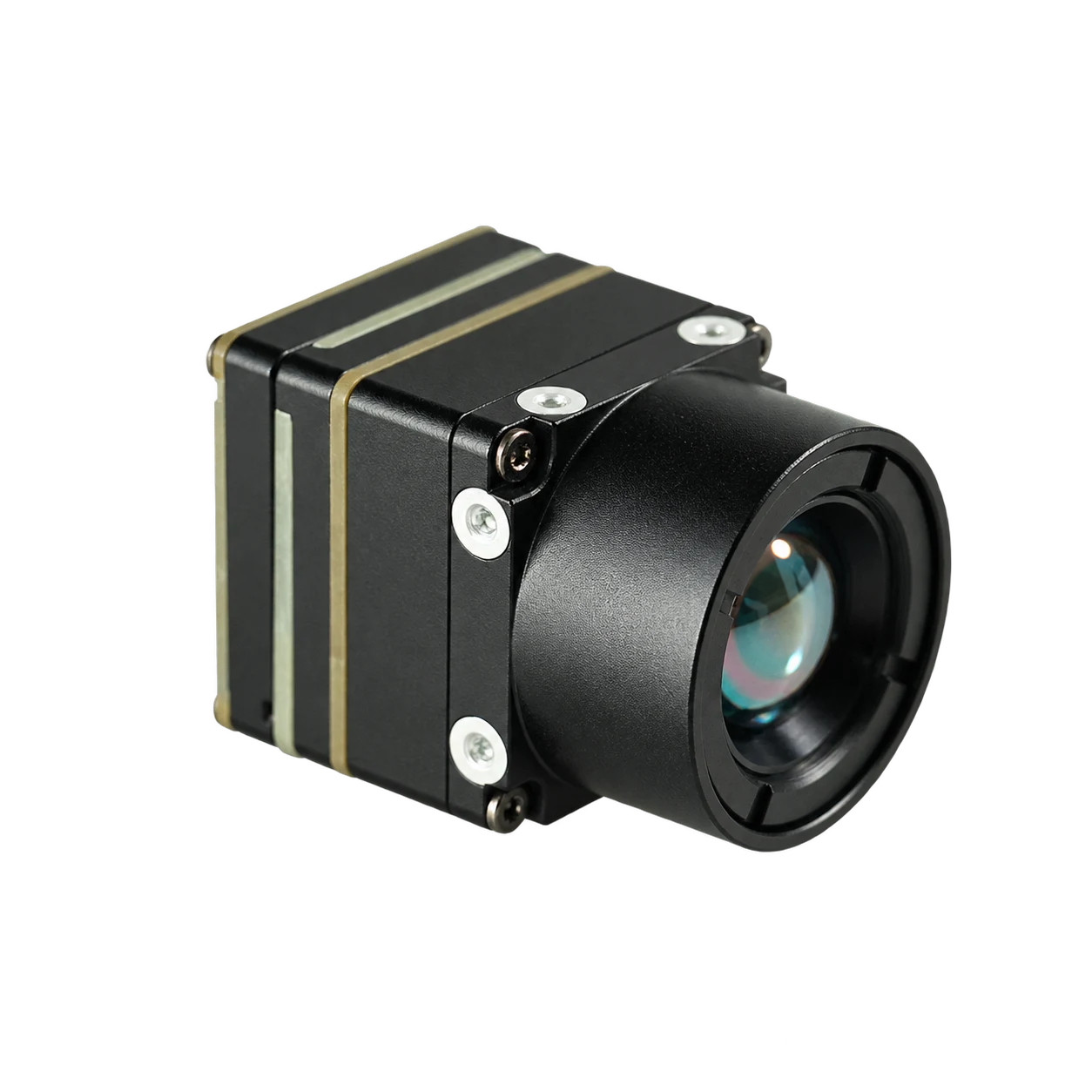
CAMCUDA AeroMini 640 × 512 Uncooled LWIR Thermal Core
The AeroMini 640 is an ultra-compact, high-performance uncooled long-wave infrared (LWIR) camera core engineered specifically for UAV payloads, DJI-type commercial drone integration, and custom stabilized gimbals. Built around a 12 μm Vanadium Oxide (VOx) microbolometer array delivering 640 × 512 resolution, the bare core weighs less than 20 grams and occupies a tiny 21 × 21 × 28 mm envelope.
Available in 60 Hz default or 30 Hz factory-configured non-radiometric imaging modes, as well as a specialized 25 Hz radiometric temperature measurement version (-20 °C to +550 °C), the AeroMini 640 features exceptional thermal sensitivity (NETD ≤ 50 mK, with optional ≤ 40 mK at 25 °C, F/1.0). With broad interface support including YUV, USB, BT.656 digital video, and CVBS analog output, it provides seamless connectivity to companion computers, flight controllers, and video links.
CAMCUDA AI VisionCube Visible & Multi-Spectral Camera Modules
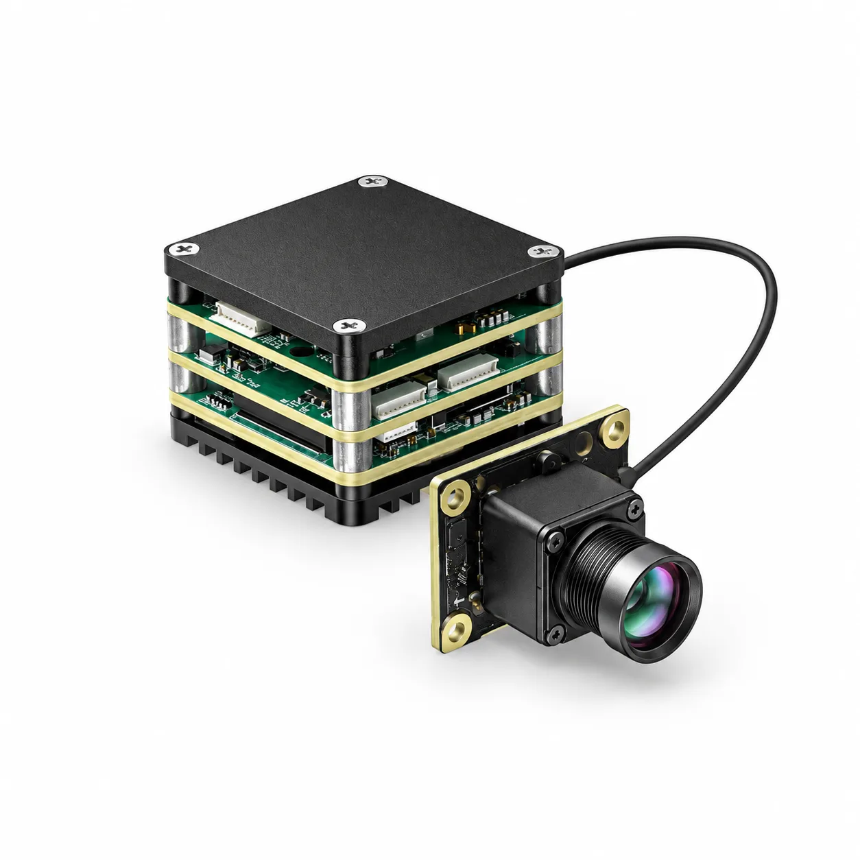
The CAMCUDA AI VisionCube is an integrated multi-spectral edge AI vision module series tailored for autonomous drone navigation, automated tracking, and industrial inspection. The product family encompasses six distinct hardware configurations spanning single visible (S), dual visible wide-angle and telephoto (D), and hybrid visible-thermal configurations (ST, DT, ST Pro, DT Pro).
Visible optical stages deliver crisp 1920 × 1080 resolution at 30 Hz using high-sensitivity CMOS sensors (up to 9650 mV/lux·s). Thermal options range from a 384 × 288 (25 Hz) array up to a professional-grade 640 × 512 (50 Hz, 12 μm pitch) uncooled LWIR core. Powered by onboard neural processing units delivering 1 TOPS (S-series) or 6 TOPS (D-series) of AI compute, the VisionCube performs real-time target recognition, autonomous tracking, and multi-sensor picture-in-picture streaming with minimal host intervention.
Comprehensive Engineering Parameter Comparison
| Parameter | CAMCUDA AeroMini 640 Core | AI VisionCube (S / D Series) | AI VisionCube (ST / DT Pro) |
|---|---|---|---|
| Detector Architecture | Uncooled VOx Microbolometer | Visible CMOS (Single 1/2.8″ or Dual 1/2.6″) | Visible CMOS + Uncooled LWIR Array |
| Resolution & Frame Rate | 640 × 512 @ 60 Hz (30 Hz opt / 25 Hz Radiometric) | 1920 × 1080 (FHD) @ 30 Hz | 1080p @ 30 Hz + 640 × 512 @ 50 Hz Thermal |
| Pixel Pitch / Spectral Band | 12 μm | 8–14 μm (LWIR) | Visible Spectrum (400–700 nm) | 12 μm Pitch | 8–14 μm LWIR |
| Thermal Sensitivity (NETD) | ≤50 mK (≤40 mK Optional at 25 °C, F/1.0) | N/A (Sensitivity: 7341–9650 mV/lux·s) | ≤50 mK (Pro Version) |
| Optical Configuration | 4 / 7 / 9 / 13 / 15 / 18 / 25 / 35 / 50 mm Lenses | 4 mm (S) / 3.9 mm Wide + 12 mm Tele (D) | Dual Visible + 9.1 mm Thermal (45.9° × 36.9°) |
| Onboard AI Compute | External Companion Computer Required | 1 TOPS (S) / 6 TOPS (D) Hardware NPU | 1 TOPS (ST) / 6 TOPS (DT Pro) Hardware NPU |
| Digital & Analog Video | YUV, USB, BT.656, CVBS (PAL/NTSC) | USB Digital Video Stream / Multi-Stream | USB Multi-Stream (Visible + Thermal + PiP) |
| Serial Telemetry & Control | UART, RS232, RS422 (Board-Dependent) | Serial UART / Control Protocol | Serial UART / Tracking Coordinate Stream |
| Core Dimensions | 21 × 21 × 28 mm (Bare Core) | 19 × 19 × 30 mm (S) / 40.8 × 25 × 26 mm (D) | 26 × 26 × 21.1 mm (Pro Thermal Module) |
| Bare Core Weight | <20 g (Excluding Optics & Flange) | Ultra-lightweight modular footprint | ≤23 g (Pro Thermal Core) / 32.4 g (Standard) |
| Operating Temperature | -40 °C to +80 °C | -20 °C to +60 °C (Industrial Grade) | -20 °C to +60 °C |
| Supply Voltage & Consumption | 5 V or 12 V (<0.5 W Typical Core Draw) | 5 V DC Nominal | 5 V / 12 V Input Configurable |
5. Digital Video Interfaces & Radiometric Calibration Workflows
Interface Bus Architectures: USB, BT.656, and Serial Protocols
Feeding raw video from a camera for drone payloads into downstream encoders, telemetry links, or onboard companion computers requires matching the right physical bus architecture to your latency requirements:
- ⚙️ USB 2.0 (UVC + CDC Control): When feeding companion hardware like an NVIDIA Jetson Orin Nano/NX, Raspberry Pi CM4, or Intel NUC, USB Video Class (UVC) is the way to go. Both the AeroMini 640 and AI VisionCube stream native YUV or MJPEG video without needing weird, proprietary kernel drivers. At the same time, an onboard CDC Virtual COM port handles ASCII or binary control commands for switching palettes (White Hot, Black Hot, IronBow, Rainbow), firing digital zoom, or triggering manual NUC shutter passes.
- ⚙️ BT.656 / DVP Parallel Interface: If your system cannot tolerate USB software stack latency, synchronous BT.656 parallel streaming delivers 8-bit or 10-bit digital video clocked alongside line-valid and frame-valid syncs directly into an onboard FPGA or dedicated H.264/H.265 hardware ASIC. This keeps end-to-end glass latency below 16 ms—crucial for high-speed obstacle avoidance and agile manual piloting.
- ⚙️ Analog Composite (CVBS / PAL / NTSC): When retrofitting legacy 5.8 GHz or 1.3 GHz analog FPV downlinks, the core can pump standard composite video straight from the carrier board, doing away with external digital-to-analog conversion modules.
- ⚙️ Serial Telemetry (UART / RS232 / RS422): Dedicated serial lines output real-time sensor diagnostics, focal plane array (FPA) temperature feedback, and tracking bounding coordinates, while taking in external hardware trigger pulses to sync multi-camera rigs.
Radiometric Calibration Pipeline & Mathematical Principles
In radiometric configurations of the AeroMini 640, pixels do not just represent relative brightness—each one corresponds to an absolute, calibrated temperature reading. To transform raw 14-bit digital signal counts into reliable engineering units across the full measurement range (-20 °C to +550 °C), the core’s digital signal processor executes real-time radiometric compensation equations:
Ttarget = [ (Sraw – (1 – ε) τatm Trefl4 – (1 – τatm) Tatm4) / (ε τatm) ](1/4)
Here is what is happening inside that equation:
- ⚙️ Sraw: The uncalibrated 14-bit digital flux value registered by the VOx pixel bridge.
- ⚙️ ε (Target Emissivity): The thermal emissivity factor of the target surface (e.g., 0.95 for electrical vinyl tape, 0.85 for weathered photovoltaic glass, 0.15 for bare polished copper busbars).
- ⚙️ τatm (Atmospheric Transmittance): The atmospheric transmission coefficient calculated dynamically based on target slant range, ambient relative humidity, and air temperature.
- ⚙️ Trefl: Reflected background radiation from nearby structures, the sky, or solar reflection.
- ⚙️ Tatm: Ambient air temperature measured along the optical line of sight.
Because ambient air temperatures change rapidly as an aircraft climbs or descends, internal hardware components expand and baseline resistance drifts. To handle this, the core runs automated Flat-Field Correction (FFC). An internal mechanical shutter closes across the detector path for approximately 250 ms, giving every pixel on the VOx array a uniform reference to recalibrate offset drift.
If you are drafting procurement specs for continuous thermal monitoring systems, review our breakdown on high-accuracy online thermal camera cores for live monitoring RFQ requirements.
6. Industrial Drone Application Benchmarks
High-Voltage Electrical Grid & Substation Inspection
Power transmission line audits require flight crews to isolate resistive splices, failing transformer bushings, and corroded disconnect switches while maintaining safe standoff distances from high-voltage corona arcing. Equipping the AeroMini 640 with an 18 mm or 25 mm telephoto lens allows pilots to maintain a comfortable 15 to 25 meter clearance from live 500 kV conductors while keeping thermal GSD well under 1 cm per pixel. Running at 60 Hz eliminates motion blur when the airframe is buffeted by turbulent crosswinds along utility rights-of-way.
Photovoltaic (PV) Solar Farm Diagnostics
Automated solar farm inspections demand strict radiometric precision that satisfies IEC 62446-3 certification. Running an AeroMini 640 radiometric module with a 9 mm optic (48.7° × 38.6° FOV) at an altitude of 40 meters provides an exact Ground Sample Distance of roughly 5.3 cm/pixel. That level of detail gives automated computer vision algorithms what they need to classify defective bypass diodes, micro-cracks, and string dropouts across utility-scale solar arrays in a single battery cycle.
Search and Rescue (SAR) & Wildfire Reconnaissance
During SAR operations in rugged wilderness or smoke-choked burn zones, standard visual cameras become dead weight. The dual-sensor AI VisionCube DT Pro integrates high-resolution thermal imaging (640 × 512 at 50 Hz) with an optical telephoto lens and an onboard 6 TOPS NPU. The module cuts through foliage canopy to spot body heat signatures, automatically places persistent bounding boxes on detected personnel, and transmits live GPS coordinates directly down the telemetry link to ground search teams.
7. Technical Integration FAQ
Can I integrate a high-resolution thermal camera for drone payloads without exceeding strict weight limits?
How do OEM payload engineers choose between standard imaging and radiometric thermal drone cameras?
📚 References & Further Reading
- Industry Standard: Workswell Advanced Thermal Imaging Systems
- Industry Standard: Wikipedia – Machine Vision
- Related Guide: Drone with Thermal Imaging: OEM Payload Core Integration Guide
- Related Guide: Thermal Master P1 Review: Technical Specs, Limitations, and OEM
- Related Guide: High-Accuracy Online Thermal Camera Core for Live Monitoring RFQ