Best Thermal Drones & OEM Camera Cores: 640×512 LWIR Selection Guide
Best Thermal Drones & OEM Camera Cores: 640×512 LWIR Selection Guide
Evaluating the best thermal drones for industrial inspection, public safety, surveillance, and defense operations means looking past the slick marketing sheets of turnkey enterprise flight frames. Here’s the deal: the real performance of any aerial thermography platform comes down to what’s sitting in the gimbal pod—the Long-Wave Infrared (LWIR) camera core. Off-the-shelf commercial thermal drones often lock you into walled-garden software ecosystems, non-modular optical setups, fixed payloads, and heavily marked-up replacement hardware. For payload engineers, drone original equipment manufacturers (OEMs), and enterprise integrators, integrating high-resolution, uncooled microbolometer cores into custom gimbals and open-standard UAV architectures provides hardware-level control, optimized Size, Weight, and Power (SWaP), and dependable radiometric accuracy.
Selecting the right thermal payload requires a grounded technical assessment of sensor resolution, pixel pitch (such as 12 μm versus modern 8 μm architectures), thermal sensitivity (Noise Equivalent Temperature Difference, NETD), optical focal length, frame rates, and electrical interface protocols. In the shop and on the flight line, these parameters dictate whether your aircraft reliably detects subtle anomalies or returns noisy, unreadable thermal feeds. This guide breaks down the operational benchmarks defining high-performance thermal imaging for unmanned aircraft systems (UAS), analyzes radiometric telemetry versus high-speed situational observation, and delivers an architectural integration roadmap using industrial-grade 640×512 LWIR OEM cores.
Table of Contents
- 👉 1. Thermal Resolution & Core Architecture: Why 640×512 LWIR is the Enterprise Benchmark
- 👉 2. Non-Radiometric vs. Radiometric Payloads: Choosing Frame Rate vs. Precision Telemetry
- 👉 3. SWaP-C Optimization & Mechanical Gimbal Integration
- 👉 4. OEM Drone Thermal Core Comparison & Technical Specifications
- 👉 5. Drone Integration Architecture: Signal Routing, Optics, and Power Rails
- 👉 6. Frequently Asked Questions (FAQ)
1. Thermal Resolution & Core Architecture: Why 640×512 LWIR is the Enterprise Benchmark
Uncooled Vanadium Oxide (VOx) focal plane arrays (FPAs) operating within the 8–14 μm long-wave infrared spectral band remain the workhorse of aerial thermal imaging. When selecting thermal hardware for an airframe, spatial resolution directly dictates the classic Johnson Criteria thresholds—Detection, Recognition, and Identification (DRI)—from realistic standoff altitudes. In practical thermography and tactical ISR, your spatial resolution determines the minimum physical feature size that maps onto the microbolometer matrix at a given Above Ground Level (AGL) altitude.
Look at entry-level consumer and light inspection drones: they frequently lean on low-resolution 160×120 (19,200 pixels) or 256×192 (49,152 pixels) sensors. In the field, those sensors hit physical limits fast. At an operational AGL of 30 to 50 meters, a low-res sensor yields a massive Ground Sampling Distance (GSD). Critical thermal anomalies—like an overheating junction clamp, a failing bypass diode on a PV string, or a target sheltered under light brush—end up subtending only a fraction of a single detector element. The camera averages that heat signature with the ambient background temperature, leading to severe thermal under-reading and missed targets.
A native 640×512 thermal resolution delivers 327,680 active detector elements. That gives you 2.96× the pixel count of an intermediate 384×288 array and over 17× the data density of an entry-grade 160×120 core. This higher geometric resolution allows pilots to hold a safe standoff distance from high-voltage transmission lines, volatile flare stacks, and tactical perimeters while maintaining enough line pairs on target for spot-on temperature calculation and shape recognition.
Beyond raw pixel counts, pixel pitch defines the physical distance between the centers of adjacent microbolometer pixels on the semiconductor die. Early aerial LWIR hardware ran on 25 μm and 17 μm nodes. Modern industrial cores have shifted down to 12 μm and sub-micron 8 μm configurations. The Instantaneous Field of View (IFOV), which specifies the angular resolving power of an individual detector element, is governed by a straightforward relationship:
IFOV (mrad) = Pixel Pitch (μm) / Focal Length (mm)
Stepping down from a 12 μm to an 8 μm pixel pitch reshapes your payload packaging. An 8 μm array needs roughly 33% less focal length to hit the identical angular field of view as a 12 μm detector. Because the clear aperture diameter of an infrared lens scales directly with focal length to maintain a fast F/1.0 aperture, smaller pixel pitches let you run thinner, lighter Germanium (Ge) or Chalcogenide glass assemblies. Integrators building long-endurance platforms routinely track these optical and detector milestones against aerospace benchmarks established by industry pioneers like BAE Systems. To examine how these detector arrays deploy across specialized missions, review our engineering overview of drone thermal camera applications.
2. Non-Radiometric vs. Radiometric Payloads: Choosing Frame Rate vs. Precision Telemetry
When laying out a custom thermal drone payload, choosing between non-radiometric and radiometric signal architectures is one of your earliest design forks. Each approach serves fundamentally different operational needs, influencing onboard digital signal processing, telemetry stream formats, and raw video frame rates.
Non-Radiometric Imaging (50 Hz / 60 Hz): Non-radiometric camera cores prioritize crisp contrast, low latency, and fluid situational feeds. Instead of calculating absolute calibrated temperatures for each pixel, onboard Digital Signal Processors (DSPs) run dynamic range compression, histogram equalization, automatic gain control (AGC), and Digital Detail Enhancement (DDE). These algorithms map raw 14-bit microbolometer data into standard 8-bit color palettes (such as White Hot, Black Hot, or Ironbow). Streaming at high refresh rates of 50 Hz to 60 Hz, these modules strip out motion blur and control latency, making them the preferred pick for:
- ✅ Real-time pilot First-Person View (FPV) navigation in zero-visibility or GPS-denied environments.
- ✅ Fast perimeter surveillance, border patrol, and dynamic target tracking.
- ✅ Wilderness Search and Rescue (SAR) sweeps where structural contrast is sufficient to spot lost individuals quickly.
Quantitative Radiometric Thermography (25 Hz / 30 Hz): Radiometric cores act as precision non-contact temperature instruments. For every single pixel across the 640×512 array, the core runs active temperature compensation equations in real time. These algorithms account for detector temperature drift, internal housing radiance, reflected ambient temperature, atmospheric transmission losses, and user-defined surface emissivity. The core streams uncompressed 14-bit or 16-bit digital temperature arrays (such as RAW radiometric frames or CDS3 formatted blocks) alongside or interleaved with the digital video feed.
Because running these multi-point calibration look-up tables and precision mathematical conversions demands substantial DSP horsepower, radiometric modules typically run at stabilized frame rates of 25 Hz or 30 Hz. Radiometric payloads are mandatory for:
- ⚙️ Substation and high-voltage transmission audits identifying resistive heating micro-faults ($\Delta T \ge 5^\circ\text{C}$).
- ⚙️ Solar PV farm mapping to isolate localized cell micro-cracks, string dropouts, and bypass diode failures.
- ⚙️ Industrial plant monitoring, oil and gas flare efficiency checks, and structural insulation loss quantification.
Plumbing these raw digital data streams into custom ground control software requires clean interface compliance. Engineers writing host-side video decoders and telemetry parsers should review standard documentation in the USB-IF Document Library to ensure robust UVC video handling and serial command parsing. If your operations span both airborne and ground-based teams, check out our complementary catalog of field observation devices.
3. SWaP-C Optimization & Mechanical Gimbal Integration
In aerial robotics, Size, Weight, Power, and Cost (SWaP-C) dictate your flight envelope. Every surplus gram mounted to an aerial gimbal triggers a cascade across the airframe: you need larger brushless motors, higher battery discharge rates, heavier ESCs, and bulkier structural carbon. Keeping payload core mass down while preserving optical performance is the cornerstone of thermal gimbal design.
Older generation thermal cores tip the scales between 40 g and 90 g without optics. Packaged into a 3-axis stabilized gimbal, the complete assembly often hits 250 g to 400 g. Next-gen uncooled cores, including the CAMCUDA AeroMini 640 (<20 g) and the ultra-miniaturized CAMCUDA SuperMini 640 (<3.5 g), change the equation entirely:
Gimbal Dynamics and Inertial Resistance: Slashing core mass by an order of magnitude pulls the payload center of gravity (CoG) tight against the pitch and yaw rotational axes. That drop in rotational inertia lets you run smaller micro-brushless motors with lower drive currents. The gimbal delivers snappier angular response, resists wind-buffet oscillations during high-speed transit, and stays thermally stable without overworking the motor windings.
Thermal Dissipation in Enclosed Pods: Uncooled microbolometer arrays are exceptionally sensitive to ambient thermal gradients across their structural housing. In compact, sealed gimbal balls or aerodynamically faired drone nosecones, heat dumping from companion companion boards (such as NVIDIA Jetson or Raspberry Pi compute modules), video transmitters, and motor drivers can induce non-uniform thermal dissipation profiles across the sensor chassis. This degrades your effective NETD. Integrators should build a direct thermal conduction path from the core chassis to the outer aluminum gimbal frame, isolate the sensor from adjacent high-heat power electronics, and maintain power rail ripple under 10 mV peak-to-peak.
4. OEM Drone Thermal Core Comparison & Technical Specifications
To help system architects and payload engineers select the right core for their airframes, the technical comparison table below details the engineering specifications of the CAMCUDA AeroMini 640 and the CAMCUDA SuperMini 640 / 640T modules.
| Technical Parameter | CAMCUDA AeroMini 640 | CAMCUDA SuperMini 640 / 640T |
|---|---|---|
| Thermal Resolution | 640 × 512 pixels | 640 × 512 pixels |
| Detector Technology | Uncooled VOx Focal Plane Array | Uncooled VOx Focal Plane Array |
| Pixel Pitch | 12 μm | 8 μm |
| Spectral Range | 8–14 μm (LWIR) | 8–14 μm (LWIR) |
| Thermal Sensitivity (NETD) | ≤50 mK @ 25°C, F1.0 (≤40 mK optional) | ≤40 mK @ 25°C, F1.0 |
| Frame Rates | 60 Hz default / 30 Hz option (Non-Rad); 25 Hz (Rad) | 640: 50 Hz (Imaging) / 640T: 30 Hz (Radiometric) |
| Core Dimensions (w/o lens) | 21 × 21 × 28 mm | 13 × 13 × 13.4 mm |
| Core Weight (w/o lens) | <20 g | <3.5 g |
| Typical Power Consumption | <0.5 W @ 25°C | ≤0.5 W @ 25°C |
| Operating Voltage | 5 V or 12 V (Board dependent; POWER_IN pins are 5V) | 3.8–5.2 V Main (Typical 5 V); +3.3 V and +1.8 V rails |
| Digital Video Interface | YUV, USB, BT.656 | 8-bit LVCMOS / BT.656, 2-lane MIPI, USB via board |
| Analog Video Output | CVBS (PAL / NTSC) | CVBS (Requires external video buffer IC) |
| Control Protocol | UART, RS232, RS422 | UART (1.8 V Logic) |
| Temperature Measurement | −20°C to +550°C (Radiometric version) | 640T: −20°C to +150°C & 100°C to +650°C |
| Athermal Lens Focal Lengths | 4, 7, 9, 13, 15, 18, 25, 35, 50 mm | 3.7, 6.1, 8.7, 11 mm |
| Operating Temperature | −40°C to +80°C | −40°C to +70°C (Industrial) |
Product Deep-Dive: CAMCUDA AeroMini 640×512 LWIR USB Thermal Core
The CAMCUDA AeroMini 640 is built for plug-and-play integration into multi-rotor inspection drones, fixed-wing mapping platforms, and industrial pan-tilt-zoom (PTZ) gimbals. Combining a proven 12 μm pixel pitch VOx detector with direct USB, BT.656, and CVBS outputs, the AeroMini 640 strikes a practical balance between sensitivity, ease of wiring, and optics availability.
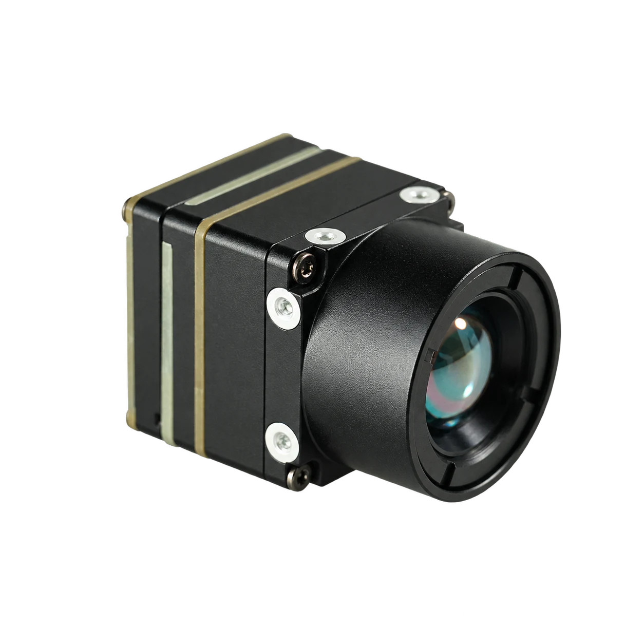
- ⚙️ High-Sensitivity Microbolometer: Uncooled 640×512 VOx sensor with a standard NETD of ≤50 mK (optional ≤40 mK grade available) for crisp resolution of fine thermal deltas in high-humidity or adverse atmospheric environments.
- ⚙️ Configurable Frame Rates: Non-radiometric variants provide smooth 60 Hz default streaming (or factory 30 Hz) for high-speed tracking, while the dedicated radiometric build runs at 25 Hz across a broad −20°C to +550°C calibrated range.
- ⚙️ Flexible Video Interfaces: Supports direct USB digital video, 8-bit BT.656, and YUV alongside analog CVBS (PAL/NTSC) for legacy analog transmitters. Serial control runs through UART, RS232, or RS422.
- ⚙️ Expansive Optical Portfolio: Offers fixed athermal lenses ranging from ultra-wide 4 mm (100°×82° FOV) for wide-area situational awareness up to 50 mm (12.5°×10° FOV) for high-altitude utility and border inspections.
- ⚙️ Low-SWaP Enclosure: Weighs under 20 g with a compact 21×21×28 mm footprint, drawing under 0.5 W at 25°C to maximize airborne battery life.
View Product Details & Pricing ➔
Product Deep-Dive: CAMCUDA SuperMini 640 / 640T Ultra-Light LWIR Module
The CAMCUDA SuperMini 640 / 640T series is engineered for extreme miniaturization. By utilizing an advanced 8 μm pixel pitch VOx detector, this module delivers full 640×512 resolution inside a minuscule 13×13×13.4 mm footprint weighing less than 3.5 grams. It is designed specifically for micro-UAVs, soldier-borne nano-drones, and ultra-compact micro-gimbals where every fraction of a gram counts.
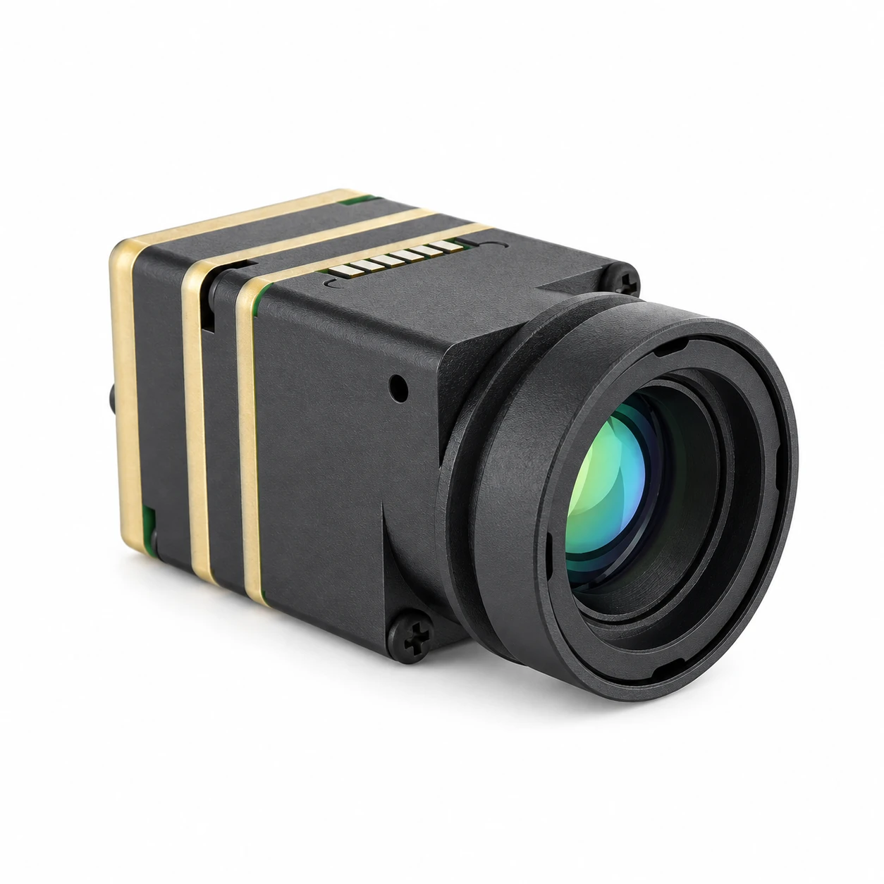
- ⚙️ Sub-Micron 8 μm Architecture: Drastically reduces Germanium lens diameters and overall optical volume while holding a sensitive ≤40 mK thermal noise floor.
- ⚙️ Dual Specialized Models:
- ✅ SuperMini 640 (Imaging Core): Delivers 50 Hz video over 8-bit LVCMOS / BT.656 and 2-lane MIPI paths for low-latency FPV piloting and reconnaissance.
- ✅ SuperMini 640T (Radiometric Core): Streams calibrated 30 Hz radiometric data over CDS3 and MIPI across dual ranges (−20°C to +150°C and +100°C to +650°C).
- ⚙️ Miniaturized Athermal Optics: Matches with custom F1.0 athermal lenses: 3.7 mm (90.0°×68.2° FOV, 2.16 mrad IFOV), 6.1 mm (46.6°×37.6° FOV), 8.7 mm (40.0°×32.2° FOV), and 11 mm (24.9°×20.0° FOV, 0.73 mrad IFOV).
- ⚙️ High-Density Interface: Mounts via a Hirose DF40C-30DP-0.4V(51) 30-pin board-to-board connector, with an optional breakout board providing standard 4-pin USB for fast bench evaluation.
- ⚙️ Sub-0.5W Power Envelope: Draws ≤0.5 W under standard operation from a clean 3.8–5.2 V supply rail.
View Product Details & Pricing ➔
5. Drone Integration Architecture: Signal Routing, Optics, and Power Rails
In the shop, embedding an uncooled LWIR core into an aerial gimbal takes strict discipline across optical sizing, signal integrity, and power rail isolation. Substandard wiring, bad ground loops, or uncalculated lens selections will instantly degrade your thermal imagery and telemetry reliability.
Lens Selection & Ground Sampling Distance (GSD) Calculations
Matching optical focal length to your mission flight profile is mandatory. Ground Sampling Distance (GSD) defines the physical distance between adjacent pixel centers mapped onto the terrain. You calculate GSD using pixel pitch ($p$), flight altitude Above Ground Level ($H$), and optical focal length ($f$):
GSD = (p × H) / f
For example, running the CAMCUDA AeroMini 640 (12 μm pixel pitch) with a 9 mm lens at an altitude of 50 meters gives you:
GSD = (12 μm × 50 m) / 9 mm = 6.67 cm per pixel
If your inspection mission requires identifying 1-centimeter hot-spots on high-voltage splices or micro-cracks in solar cells from 50 meters AGL, a 9 mm optic will not provide enough pixels on target. You need to step up to a 25 mm or 35 mm lens, which narrows your field of view but delivers the optical magnification needed for accurate diagnostic work.
Power Conditioning and Noise Isolation
Microbolometer Read-Out Integrated Circuits (ROICs) operate by detecting microvolt-level resistance shifts across uncooled VOx bridge membranes as they absorb infrared energy. If high-frequency switching noise from drone Electronic Speed Controllers (ESCs), brushless gimbal motors, or RF datalinks bleeds into the camera supply rail, it shows up immediately as fixed-pattern noise (FPN), crawling horizontal bars, or digital salt-and-pepper artifacts across your video feed.
Follow these layout and power rules to keep your thermal feed clean:
- ⚙️ Dedicated Low-Dropout Regulators (LDOs): Never power an LWIR core directly from a main flight pack or a noisy buck regulator. Use dedicated, high-PSRR linear regulators to generate the 5.0 V, 3.3 V, and 1.8 V rails. Keep rail ripple below 10 mV peak-to-peak on main inputs and under 1 mV RMS on sensitive analog lines.
- ⚙️ Controlled-Impedance Digital Routing: When using high-speed digital paths like 2-lane MIPI CSI-2 or parallel LVCMOS/BT.656, maintain strict 100 Ω differential trace impedance. Keep trace lengths under 50 mm between the Hirose connector and the host carrier board to prevent EMI issues and signal degradation.
- ⚙️ Analog Output Buffering: When routing CVBS analog video from the SuperMini 640 into a 5.8 GHz analog transmitter, always place an external 75 Ω video buffer IC on the carrier board. The bare core pin cannot drive low-impedance coaxial lines directly without signal clipping.
For commercial procurement details, warranty terms, and return procedures, check out our standardized commercial refund policy.

6. Frequently Asked Questions (FAQ)
Why are proprietary enterprise thermal drones so expensive compared to modular OEM core integration?
What is the practical operational difference between 12 μm and 8 μm pixel pitch thermal cores?
When should an engineer choose a 50/60 Hz imaging core over a 25/30 Hz radiometric core?
How does Noise Equivalent Temperature Difference (NETD) impact aerial thermal inspection reliability?
What are the power conditioning requirements when integrating an uncooled LWIR core into a drone?
📚 References & Further Reading
- Industry Standard: BAE Systems
- Industry Standard: USB-IF Document Library
- Related Guide: Drone Thermal Camera Integration Guide
- Related Guide: Field Observation Devices & Handheld Optics
- Related Guide: Commercial Warranty & Refund Policy