Infrared Drone Camera Selection Guide: 640×512 LWIR Modules for OEM UAV Payloads
Infrared Drone Camera Selection Guide: 640×512 LWIR Modules for OEM UAV Payloads
If you have ever spent a week on the test bench trying to squeeze an extra three minutes of flight time out of a sub-2-kilo quadrotor, you already know the brutal reality of aerial engineering: payload design is an uncompromising war over Size, Weight, Power, and Cost (SWaP-C). When you integrate an infrared drone camera core into an airborne electro-optical/infrared (EO/IR) turret, you cannot just grab a sensor, bolt it into a 3D-printed housing, and hope for clean thermals. You are juggling focal plane array (FPA) pixel pitch, complex athermal optical stacks, conducted thermal dissipation paths, switching noise on sensitive electrical rails, and deterministic digital video pipelines with zero tolerance for dropped frames.
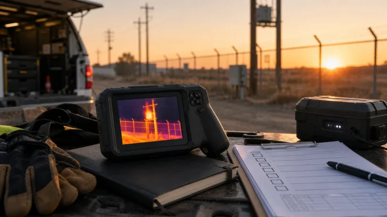
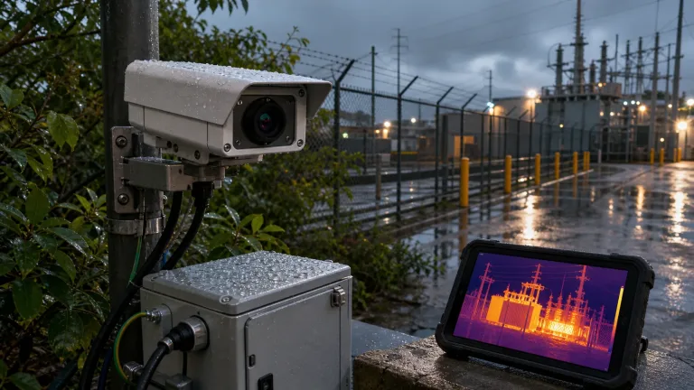
Whether your airframe is flying autonomous night-time ISR, perimeter security sweeps, wildland search-and-rescue (SAR), high-voltage utility audits, or crop stress mapping, you need an uncooled Long-Wave Infrared (LWIR) core that delivers verified Noise Equivalent Temperature Difference (NETD) sensitivity and rock-solid frame timing straight into your edge compute. Historically, we had to choose between clunky, power-hungry radiometric bricks and grainy, low-res analog cores. That trade-off is dead. Modern 640×512 uncooled Vanadium Oxide (VOx) arrays—built on mature 12 μm and cutting-edge 8 μm nodes—have completely rewritten payload architecture. This guide breaks down the hard numbers, optical calculations, electrical gotchas, and mechanical integration strategies you need to package 640×512 LWIR cores into production-ready micro-gimbals and fixed-wing airframes.
Table of Contents
- 👉 1. Core Detector Architecture: 8 μm vs. 12 μm VOx Focal Plane Arrays
- 👉 2. Optics Selection, IFOV Calculations, and Aerial DRI Modeling
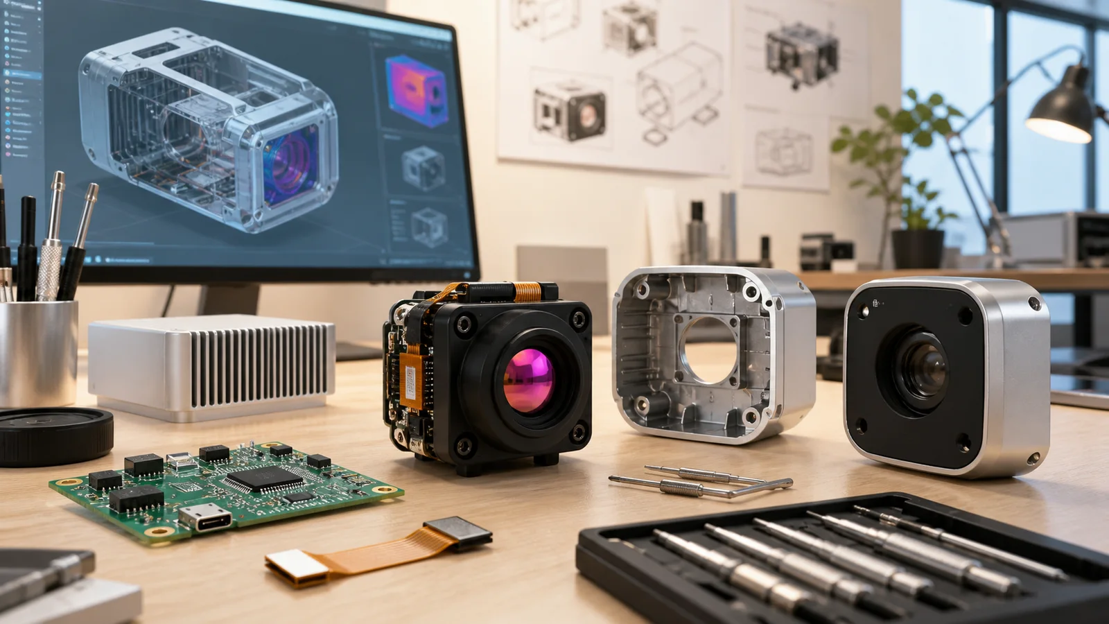
- 👉 3. Mechanical & SWaP Optimization for Micro-Gimbal Enclosures
- 👉 4. Electrical Protocols, Digital Video Interfaces & Edge Processing
- 👉 5. Non-Uniformity Correction (NUC) & Radiometric Thermography
- 👉 6. CAMCUDA AeroMini 640 Compact LWIR Thermal Camera Module
- 👉 7. CAMCUDA SuperMini 640 / 640T Ultra-Light LWIR Thermal Camera Module
- 👉 8. Comprehensive CAMCUDA 640×512 Module Comparison Matrix
- 👉 9. UAV Integration FAQ & Technical Deep-Dive
1. Core Detector Architecture: 8 μm vs. 12 μm VOx Focal Plane Arrays
Look under the hood of any high-performance airborne thermal imager, and the detector material tells you immediately what kind of performance you can expect. In the shop, we avoid amorphous Silicon (α-Si) for high-dynamic flight profiles. Vanadium Oxide (VOx) microbolometer arrays are the gold standard for aerial platforms. Why? VOx provides a markedly higher Temperature Coefficient of Resistance (TCR), lower 1/f electronic noise, and much faster thermal time constants (typically running ≤10–12 ms). When your drone hits a crosswind gust or executes a rapid 60-degree-per-second yaw rotation, a fast thermal time constant is the difference between a crisp, actionable infrared frame and a smeared mess of thermal ghosting.
When you lock in a 640×512 resolution, your primary hardware fork in the road is pixel pitch: traditional 12 μm versus next-gen sub-10-micron 8 μm fabrication. This single choice cascades through your entire mechanical assembly, determining the weight of your front optical glass, your gimbal inertia, and your thermal dissipation strategy.
Let’s run through the physics. A 12 μm 640×512 focal plane array spans an active sensor area of 7.68 mm × 6.14 mm with an array diagonal of roughly 9.83 mm. Because each individual pixel has a relatively generous surface area (144 μm²), it gathers a healthy volume of thermal photons per frame integration window. This makes achieving high thermal sensitivity (NETD ≤50 mK standard, and ≤40 mK on tuned cores) straightforward with standard fast aperture (F/1.0) optics. For medium-to-high altitude UAV missions—like fixed-wing border surveillance or mid-altitude pipeline monitoring—a 12 μm core paired with a 25 mm to 75 mm lens gives you unbeatable optical reach and high resolving power. If you want a broader perspective on how these uncooled platforms compare across industrial and security roles, check out our in-depth analysis on uncooled LWIR thermal modules for outdoor security and industrial monitoring.
Now, here is the deal with the newer 8 μm pixel pitch: shrinking the pitch down to 8 μm drops your active sensor dimensions to 5.12 mm × 4.09 mm, with a diagonal of just 6.55 mm. That is a massive 55% reduction in total sensor surface area. For a drone payload engineer, this reduction delivers an enormous optical weight bonus. Because the FPA is physically smaller, you can achieve the exact same Field of View (FOV) using an optical focal length that is 33% shorter. A shorter focal length means your Germanium front elements shrink in both clear aperture diameter and center thickness. Considering that optical glass accounts for anywhere from 60% to 80% of an airborne camera’s total mass, moving to an 8 μm core allows you to build complete dual-sensor micro-gimbals weighing under 50 grams without compromising your 640×512 pixel count.
2. Optics Selection, IFOV Calculations, and Aerial DRI Modeling
Selecting the right glass for an airborne thermal payload is an exercise in optical compromise. You are constantly balancing Instantaneous Field of View (IFOV), overall scene coverage (HFOV × VFOV), and the real-world Detection, Recognition, and Identification (DRI) ranges defined by the classical Johnson Criteria. In the field, you calculate spatial sampling resolution at your sensor plane using the standard formula:
IFOV (mrad) = [Pixel Pitch (μm) / Focal Length (mm)]
A smaller IFOV gives you more pixels on target at long standoff distances. But there is no free lunch: tightening your IFOV via longer focal lengths shrinks your overall field of view. That makes close-quarters situational awareness tough and puts a huge burden on your gimbal’s stabilization loop to filter out high-frequency aircraft vibrations.
Optical Profiles for UAV Mission Profiles
- ⚙️ Wide-Angle Navigation & Obstacle Avoidance (3.7 mm to 9 mm Optics): Perfect for low-altitude micro-FPV flights, close-range structural inspections, and collision avoidance in GPS-denied environments. For instance, pairing an 8 μm sensor with a 3.7 mm F1.0 athermal lens gives you an expansive 90.0° × 68.2° FOV with an IFOV of 2.16 mrad. It provides total situational awareness when piloting through indoor structures or under bridge decks.
- ⚙️ Balanced Medium-Range Inspection (8.7 mm to 18 mm Optics): The workhorse configuration for solar farm inspection, high-voltage utility pole monitoring, and building envelope audits where your aircraft maintains a safe standoff distance of 15 to 50 meters. A 12 μm core with a 9 mm F1.0 lens gives you a 48.7° × 38.6° FOV, while an 8 μm core paired with an 8.7 mm lens delivers a 40.0° × 32.2° FOV with a tight 0.92 mrad IFOV.
- ⚙️ Long-Range Standoff Reconnaissance (25 mm to 75 mm Optics): Built for high-altitude ISR, perimeter protection, and wildland search-and-rescue. Long focal lengths project critical target pixels across human and vehicular targets at distances well over 1,000 meters. If you need wide-area coverage with extreme spatial fidelity, you should also look into 1280×1024 high-resolution uncooled LWIR cores to maximize swath width without sacrificing resolution.
Optical Athermalization for Aerial Environments
Airborne payloads face brutal thermal swings. An aircraft can sit on a sun-baked tarmac at +40 °C and climb to 3,000 feet where the ambient air is −10 °C in under five minutes. In the LWIR band, Germanium (Ge) has an extremely aggressive thermal coefficient of refractive index (dn/dT ≈ 396 × 10⁻⁶ /°C at 10.6 μm). If your lens barrel is not passively athermalized, thermal expansion of the aluminum or titanium housing combined with the refractive index shift in the glass will pull your focal plane completely out of focus, turning your sharp video into a blurry smear.
High-reliability drone thermal cameras use passive optical athermalization. By pairing positive and negative thermal dispersion optical elements (combining Germanium, Chalcogenide glasses, and Zinc Selenide) within mechanically compensated housings, the optical system maintains sharp focus across the entire −40 °C to +80 °C operating range without adding heavy, power-hungry motorized autofocus assemblies. If you want to dive deeper into precision infrared optical assemblies, check out the engineering work done by the teams at Sierra-Olympic Technologies.
3. Mechanical & SWaP Optimization for Micro-Gimbal Enclosures
When you are designing micro-gimbals, every single gram and milliwatt counts. If your payload ball is too heavy, your brushless motors have to draw more current to hold position, draining the flight pack and introducing low-frequency motor jitter that ruins your video stability.
Key Mechanical & Environmental Design Rules:
- ✅ Conduction Over Convection: Micro-gimbal payload spheres are sealed against dust and moisture (rated IP64 to IP67). That means zero convective cooling inside the ball. You must conduct heat away from the camera chassis into the outer aluminum gimbal yoke using a high-performance thermal interface material (TIM) with a thermal conductivity rating of at least 3.0 W/m·K.
- ✅ Symmetrical Thermal Dissipation: Uneven heat sinking across the microbolometer housing causes localized thermal gradients on the FPA. These gradients create spatial non-uniformity drifts across the image, forcing the camera to perform disruptive shutter calibrations (NUC clicks) during flight. Always design balanced, symmetrical clamping and heat dissipation paths.
- ✅ Vibration and Shock Hardening: Drone airframes generate aggressive high-frequency micro-vibrations (typically 100 Hz to 2.5 kHz) driven by motor commutation and prop blade-pass dynamics. Relying on friction-fit ribbon cables is asking for an in-flight failure. Use positive-locking, high-density board-to-board connectors—like the Hirose DF40C-30DP-0.4V(51) 30-pin interface—to ensure rock-solid data integrity under multi-axis G-loads.
- ✅ Minimizing Payload Ball Inertia: Integrating an ultra-light core (like the sub-3.5 g CAMCUDA SuperMini 640) cuts the payload sphere’s moment of inertia dramatically. This allows smaller, lighter gimbal motors to achieve high stabilization bandwidths (>50 Hz) while drawing minimal power from your flight pack.
4. Electrical Protocols, Digital Video Interfaces & Edge Processing
Connecting your infrared drone camera core to onboard flight controllers, edge AI processors, and RF downlinks requires picking the right electrical interface for the job. Your choice dictates latency, processor utilization, and wiring weight across your gimbal slip rings.
Digital Video Protocols for Aerial Computing
If your drone runs onboard edge AI for object detection, autonomous tracking, or semantic segmentation using hardware like the NVIDIA Jetson Orin Nano or Raspberry Pi CM4, 2-lane MIPI CSI-2 is the clear winner. MIPI feeds uncompressed 14-bit radiometric data or pre-processed YUV frames straight into the processor’s image signal processing (ISP) pipeline via Direct Memory Access (DMA). This bypasses the latency, CPU load, and USB packet jitter that can bog down onboard computer vision.
For custom hardware architectures using dedicated FPGAs, video encoders, or custom RF transmitters, clock-synchronous 8-bit BT.656 and LVCMOS buses provide deterministic, uncompressed streaming with zero protocol overhead. On small micro-drones where basic collision avoidance is the only requirement, you can even explore ultralight options like the TC160-NF 160×120 miniature thermal core to save space and compute bandwidth.
Analog FPV Downlinks & Power Regulation
For manual FPV piloting and rapid search tasks, composite analog video (CVBS / PAL / NTSC) is still widely used because it delivers essentially zero latency over standard 5.8 GHz analog video transmitters. One critical hardware detail: check whether your thermal core provides an internally buffered 75 Ω output or requires an external video amplifier on your gimbal carrier PCB.
Clean power is non-negotiable. Microbolometer read-out integrated circuits (ROICs) are extremely sensitive to high-frequency switching hash from electronic speed controllers (ESCs) and onboard buck converters. Your main 5V supply rail must maintain ripple noise below 10 mV peak-to-peak. For dedicated analog core rails (such as 1.8V supplies), you need ultra-low-noise Low-Dropout (LDO) regulators with RMS noise ratings ≤1 mV from 1 Hz to 50 kHz. Serial telemetry and camera commands run over standard UART links; if your flight controller runs 3.3V or 5V logic, remember to include bidirectional level shifters to protect 1.8V core UART lines.
5. Non-Uniformity Correction (NUC) & Radiometric Thermography
Every uncooled microbolometer array leaves the cleanroom with slight individual variations in pixel resistance and responsivity. Without calibration, your image would look like a wall of static. To fix this, modern thermal modules run real-time 2-point Non-Uniformity Correction (NUC) and Bad Pixel Replacement (BPR) on their onboard image processors.
As your drone flies through changing air currents, the camera’s internal temperature fluctuates, causing baseline offset drift across the FPA. The camera corrects for this using an internal mechanical solenoid shutter that closes for 200–400 ms to refresh the flat-field baseline. In fast tactical operations or autonomous target tracking where a momentary video freeze could break an algorithm’s lock, you can switch the module to Shutterless Scene-Based NUC (SBNUC), which dynamically updates pixel drift corrections by analyzing scene motion and optical flow.
Visual Contrast vs. Calibrated Radiometric Data
When selecting your core, be clear about whether your mission needs qualitative visual imaging or quantitative radiometric temperature measurement:
- ⚙️ Imaging-Only Cores (e.g., AeroMini 640 @ 60 Hz / CAMCUDA SuperMini 640 @ 50 Hz): These modules push raw detector data through dynamic tone mapping and Digital Detail Enhancement (DDE) engines. The output is an optimized 8-bit visual feed (White-Hot, Black-Hot, or false-color palettes) tuned for high scene contrast and maximum frame rates (50–60 Hz), eliminating motion blur during aggressive flight maneuvers.
- ⚙️ Radiometric Thermography Cores (e.g., AeroMini 640 @ 25 Hz / CAMCUDA SuperMini 640T @ 30 Hz): These units calculate and output absolute, calibrated surface temperature values for every single pixel in the 640×512 frame. The CAMCUDA SuperMini 640T gives you dual-band radiometric coverage:
- ✅ Low-Temperature Range: −20 °C to +150 °C (optimized for building audits, search and rescue, animal tracking).
- ✅ High-Temperature Range: 100 °C to +650 °C (engineered for industrial flare stacks, solar PV hotspot inspections, power grid monitoring, and wildland firefighting).
If you want to stay up to date on machine vision protocols and thermal sensor standards, take a look at the technical papers on Vision Systems Design.

CAMCUDA AeroMini 640 Compact LWIR Thermal Camera Module
The CAMCUDA AeroMini 640 is an uncooled VOx thermal camera core built around a 640 × 512 focal plane array with a 12 μm pixel pitch and an 8–14 μm spectral response. Designed as a rugged drop-in core for multi-rotor UAV payloads, pan-tilt turrets, and embedded robotics, the AeroMini 640 combines proven NETD thermal sensitivity (≤50 mK standard, with ≤40 mK optional builds) with extremely low power dissipation (<0.5 W typical).
The module comes in two distinct factory hardware versions: a 60 Hz non-radiometric imaging configuration built for smooth video, rapid target tracking, and situational awareness; and a 25 Hz radiometric thermography version calibrated for precise temperature measurement from −20 °C to +550 °C (available with factory-calibrated 9 mm, 13 mm, and 18 mm optics).
Comprehensive Specifications: AeroMini 640
| Parameter | AeroMini 640 Specification Value | Integration Notes |
|---|---|---|
| Detector Type & Resolution | Uncooled VOx, 640 × 512 pixels | High-stability Vanadium Oxide microbolometer |
| Pixel Pitch & Spectral Band | 12 μm | 8–14 μm (LWIR) | Standard long-wave atmospheric transmission window |
| Thermal Sensitivity (NETD) | ≤50 mK @ 25 °C, F/1.0 (≤40 mK optional) | Measures thermal contrast sensitivity |
| Frame Rate Options | 60 Hz (Non-radiometric) / 25 Hz (Radiometric) | 60 Hz delivers smooth video for high-speed flight |
| Digital Video Outputs | YUV, USB, BT.656 | Compatible with onboard companion computers & FPGAs |
| Analog Video Output | CVBS, PAL, NTSC | Direct interface to 5.8 GHz analog video downlinks |
| Serial Communication | UART, RS232, RS422 | Standard serial control for autopilot & gimbal MCU |
| Operating Voltage & Power | 5 V or 12 V configuration | <0.5 W typ. @ 25 °C | Low power dissipation reduces gimbal heat accumulation |
| Dimensions & Bare Weight | 21 × 21 × 28 mm | <20 g | Excludes lens and mounting flange envelope |
| Temperature Range | −20 °C to +550 °C (Radiometric version) | Available with 9 mm, 13 mm, and 18 mm optical builds |
| Operating & Storage Temp | Operating: −40 °C to +80 °C | Storage: −50 °C to +85 °C | Industrial aerospace-grade operating envelope |
| Available Optics (F/1.0) | 4, 7, 9, 13, 15, 18, 25, 35, 50, 60, 75 mm | 9 mm configuration specifies 48.7° × 38.6° H×V coverage |
CAMCUDA SuperMini 640 / 640T Ultra-Light LWIR Module
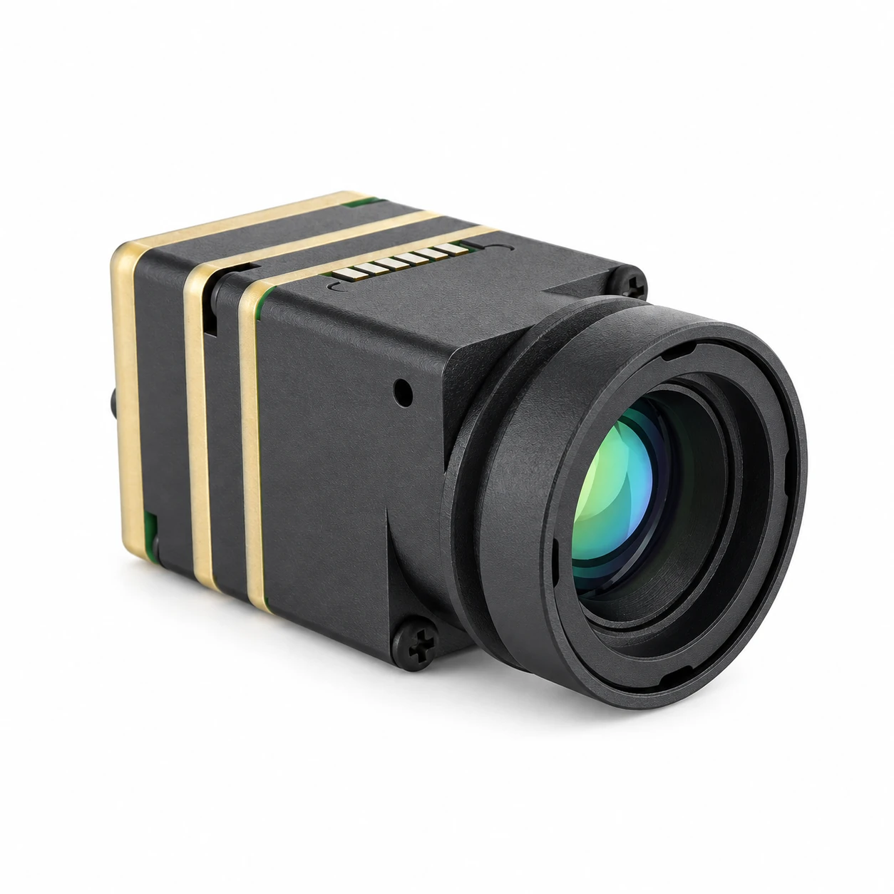
The CAMCUDA SuperMini 640 / 640T is built for payloads where every fraction of a gram matters. Combining a 640 × 512 uncooled VOx FPA on an advanced 8 μm pixel pitch with an ultra-compact 13 × 13 mm chassis, this bare core weighs less than 3.5 grams. Designed specifically for micro-UAV turrets, pocket reconnaissance drones, and space-constrained avionics, it delivers full 640-resolution thermal imagery with an impressive NETD of ≤40 mK at F1.0 while pulling ≤0.5 W.
The series offers two factory-configured hardware models:
- ⚙️ CAMCUDA SuperMini 640 (Imaging Only): Runs at a fast 50 Hz with 8-bit LVCMOS / BT.656 and 2-lane MIPI paths for low-latency visual contrast and flight piloting.
- ⚙️ CAMCUDA SuperMini 640T (Thermographic): Operates at 30 Hz with CDS3 and MIPI temperature streams, calibrated for dual-band radiometric thermography (−20 °C to +150 °C and 100 °C to +650 °C).
Athermal Optical Configurations: CAMCUDA SuperMini 640
| Optical Configuration | Focal Length & Aperture | Field of View (H × V) | IFOV (Spatial Resolution) |
|---|---|---|---|
| Wide Angle Lens | 3.7 mm, F1.0 Athermal | 90.0° × 68.2° | 2.16 mrad |
| Wide Field Lens | 6.1 mm, F1.0 Athermal | 46.6° × 37.6° | 1.31 mrad |
| Balanced Field Lens | 8.7 mm, F1.0 Athermal | 40.0° × 32.2° | 0.92 mrad |
| Narrow Field Lens | 11.0 mm, F1.0 Athermal | 24.9° × 20.0° | 0.73 mrad |
Electrical Interface & Power Requirements
| Electrical Path | Published Requirement | UAV Gimbal Integration Note |
|---|---|---|
| MAIN_POWER | 3.8–5.2 V (Typical 5.0 V) | Maximum 10 mV p-p supply ripple noise |
| +3.3 V Power Rail | 3.28 V to 3.32 V | Maximum 10 mV p-p ripple noise |
| +1.8 V Power Rail | 1.78 V to 1.82 V | Ultra-clean supply: 1 mV RMS max (1 Hz to 50 kHz) |
| Digital Video | 8-bit LVCMOS / 2-lane MIPI CSI-2 | 640: BT656 video · 640T: CDS3 radiometric stream |
| Serial Command & Control | UART (1.8 V logic levels) | Requires level shifting when connecting to 3.3V/5V MCUs |
| Analog Video (CVBS) | Dedicated CVBS pin | Requires an external 75 Ω video-buffer IC on carrier board |
| Physical Interface | Hirose DF40C-30DP-0.4V(51) 30-pin | Optional TMS6102V100F022 board converts to 4-pin USB |
8. Comprehensive CAMCUDA 640×512 Module Comparison Matrix
To help you nail down the right uncooled LWIR core for your airframe’s payload envelope, here is the full engineering comparison between the CAMCUDA AeroMini 640 and the CAMCUDA SuperMini 640 / 640T platforms:
| Specification Parameter | CAMCUDA AeroMini 640 Compact | CAMCUDA SuperMini 640 / 640T |
|---|---|---|
| Array Resolution | 640 × 512 pixels | 640 × 512 pixels |
| Pixel Pitch | 12 μm | 8 μm |
| Detector Technology | Uncooled VOx Focal Plane Array | Uncooled VOx Focal Plane Array |
| Spectral Range | 8 to 14 μm (LWIR) | 8 to 14 μm (LWIR) |
| Core Dimensions (W × H × D) | 21 × 21 × 28 mm (w/o lens) | 13 × 13 × 13.4 mm (w/o lens) |
| Bare Core Weight | <20 grams | <3.5 grams |
| Thermal Sensitivity (NETD) | ≤50 mK @ 25 °C, F1.0 (≤40 mK optional) | ≤40 mK @ 25 °C, F1.0 |
| Frame Rate Models | 60 Hz (Imaging) / 25 Hz (Radiometric) | 50 Hz (CAMCUDA SuperMini 640) / 30 Hz (CAMCUDA SuperMini 640T) |
| Power Consumption | <0.5 W (Typical @ 25 °C) | ≤0.5 W (Typical @ 25 °C) |
| Supply Voltage Rails | 5 V or 12 V configuration | Main: 3.8–5.2 V (Typ 5V); Rails: +3.3V, +1.8V |
| Digital Video Interfaces | YUV, USB, BT.656 | 8-bit LVCMOS / BT656, 2-lane MIPI CSI-2, USB |
| Analog Video Output | Native CVBS (PAL / NTSC) | CVBS Pin (Requires external buffer IC) |
| Serial Command & Control | UART, RS232, RS422 | UART (1.8 V logic levels) |
| Radiometric Temperature Measurement | −20 °C to +550 °C (9 / 13 / 18 mm optics only) | −20 °C to +150 °C & 100 °C to +650 °C (640T only) |
| Available Standard Optics | 4, 7, 9, 13, 15, 18, 25, 35, 50, 60, 75 mm | 3.7 mm, 6.1 mm, 8.7 mm, 11.0 mm (Athermalized) |
| Operating Temperature Range | −40 °C to +80 °C | −40 °C to +80 °C |
9. UAV Integration FAQ & Technical Deep-Dive
How do I choose between an imaging-only and a radiometric infrared drone camera module?
If your mission profile is focused on search and rescue (SAR), tactical reconnaissance, nighttime navigation, or perimeter sweeps, an imaging-only core (like the AeroMini 640 60 Hz or CAMCUDA SuperMini 640 50 Hz) is the right tool. These modules process raw microbolometer data through Dynamic Detail Enhancement (DDE) and real-time histogram equalization to deliver maximum visual contrast between warm targets and cold backgrounds. Running at 50–60 Hz, they eliminate the motion blur and video latency that can disrupt high-speed flight maneuvers.
On the flip side, if your drone is performing predictive maintenance on high-voltage power lines, inspecting utility-scale solar arrays for dead cells, auditing industrial flare stacks, or running precision agricultural moisture analysis, you need a radiometric module (like the AeroMini 640 25 Hz or CAMCUDA SuperMini 640T 30 Hz). These modules output calibrated temperature matrices (such as −20 °C to +150 °C and 100 °C to +650 °C on the CAMCUDA SuperMini 640T). Because they perform complex multi-point temperature lookup calibrations per frame, their refresh rates typically top out at 25–30 Hz.
Which digital video interfaces and protocols are best suited for UAV gimbal integration?
If you are running onboard edge computing for autonomous computer vision (using platforms like NVIDIA Jetson Orin Nano, Jetson Xavier NX, or Raspberry Pi CM4), 2-lane MIPI CSI-2 is by far your best option. MIPI pushes uncompressed 14-bit radiometric frames or pre-processed YUV video directly into the host system’s memory via Direct Memory Access (DMA). This bypasses the USB stack entirely, cutting latency, eliminating packet jitter, and freeing up CPU cycles for your neural networks.
If you are streaming into an FPGA-based image processing board, a hardware H.264/H.265 video encoder, or a custom digital RF link, 8-bit BT.656 or LVCMOS gives you deterministic, clock-synchronous parallel streaming with zero software driver overhead. For analog FPV piloting setups running over 5.8 GHz video transmitters, standard CVBS composite video is preferred for its near-zero latency. Just remember: while the AeroMini 640 outputs a native CVBS signal, the CAMCUDA SuperMini 640 core requires an external 75 Ω video-buffer amplifier on your carrier PCB. For command and telemetry (palette switches, digital zoom, NUC triggers), standard UART is used—make sure to level-shift 1.8V core UART logic if your flight controller runs on 3.3V or 5V rails (e.g., ArduPilot or PX4 autopilots).
How do SWaP (Size, Weight, and Power) constraints affect drone thermal payload design?
Germanium lenses are dense, making optics the heaviest part of any thermal camera. A traditional 12 μm core with a 25 mm lens can weigh between 80 and 120 grams, requiring larger gimbal motors and drawing more battery power. By comparison, an 8 μm core like the CAMCUDA SuperMini 640 weighs under 3.5 grams (bare core) and achieves identical fields of view using lenses that are 33% shorter in focal length. This keeps your total combined optical and core payload weight under 15 to 20 grams, making it easy to integrate into sub-250g micro-drones or compact dual-sensor turrets.
On the power side, both the AeroMini 640 and CAMCUDA SuperMini 640 cores consume ≤0.5 W under typical operation at 25 °C. This low draw prevents battery drain and eliminates heat buildup inside sealed payload spheres. Just make sure your power delivery provides clean DC rails with ripple noise under 10 mV peak-to-peak to avoid injecting electronic noise into the sensitive VOx microbolometer array.
📚 References & Further Reading
- Industry Standard: Vision Systems Design – Technical insights on embedded machine vision, thermal sensors, and industrial imaging protocols.
- Industry Standard: Sierra-Olympic Technologies – Reference resources on optical athermalization, infrared camera cores, and airborne payload engineering.
- Related Guide: Uncooled LWIR Thermal Modules for Outdoor Security & Industrial Monitoring – Architectural trade-offs across uncooled thermal sensors.
- Related Guide: HR 1280 (1280×1024) High-Resolution Uncooled LWIR Core – High-definition thermal imaging for broad-area aerial ISR.
- Related Guide: TC160-NF (160×120) Miniature Thermal Module – Ultra-compact thermal solution for basic obstacle avoidance systems.