Selecting a Compact Thermal Imaging Camera: OEM Module Guide for Embedded & UAV Integration
Selecting a Compact Thermal Imaging Camera: OEM Module Guide for Embedded & UAV Integration
For systems engineers, optomechanical designers, and robotics hardware leads, selecting a compact thermal imaging camera means matching the detector, optics, electronics and enclosure to one application. Miniaturized Long-Wave Infrared (LWIR) cores can reduce the space needed for thermal sensing, but a small bare module is only the starting point for a complete embedded or airborne camera.
When the mechanical envelope shrinks, thermal dissipation, optical aperture, Instantaneous Field of View (IFOV), connector clearance and supply stability deserve early attention. A battery-powered drone gimbal, handheld diagnostic tool and remote IoT sensor may need very different resolutions, interfaces and measurement capabilities.
This guide works through microbolometer architecture, optical geometry, SWaP budgets and host interfaces before comparing current CAMCUDA AeroMini and SuperMini configurations. It keeps high-resolution imaging separate from low-resolution, low-power sensing so you can choose an evaluation path, document the missing evidence and validate the complete system before committing to a PCB or enclosure.
Table of Contents
- 👉 1. Anatomy of a Compact LWIR Core: VOx vs. a-Si, Pixel Pitch, and WLP
- 👉 2. Optical Engineering: Calculating FOV, IFOV, and DRI for Compact Payloads
- 👉 3. SWaP Optimization: Thermal Dissipation, Mass Budgets, and UAV Dynamics
- 👉 4. Embedded Interface Protocols: MIPI CSI-2, SPI, USB, and BT.656 Direct Capture
- 👉 5. Product Benchmarking: High-Resolution Imaging vs. Low-Power Sensing
- 👉 6. Mechanical, Power Sequencing, and Radiometric Calibration Integration
- 👉 7. Deep-Dive OEM Integration FAQ
1. Anatomy of a Compact LWIR Core: VOx vs. a-Si, Pixel Pitch, and WLP
Uncooled LWIR modules commonly sense in the 8–14 μm band, which includes the thermal-emission peak of many everyday-temperature objects. Visible-light CMOS sensors convert absorbed photons into electrical charge. A microbolometer instead detects a temperature rise caused by absorbed infrared energy.
Each pixel uses a thermally isolated sensing structure whose electrical resistance changes with temperature. The Readout Integrated Circuit (ROIC) measures the response, and the camera electronics correct and process the array into an image. Digital bit depth and the availability of calibrated temperature data depend on the detector, electronics and camera version.
The sensing material is one architectural choice, but compare measured performance under matching test conditions rather than ranking finished cameras by material alone:
- ⚙️ Vanadium Oxide (VOx): VOx is an established microbolometer technology used in both current CAMCUDA families below. Review the selected detector’s Noise Equivalent Temperature Difference (NETD), response time, uniformity and power. An advertised NETD needs its temperature, F-number, frame-rate and processing conditions where available.
- ⚙️ Amorphous Silicon (a-Si): Amorphous silicon is another established thermoresistive detector technology. Material processing, pixel structure and readout design affect sensitivity and noise; a-Si does not impose one universal NETD band or require a particular amount of temporal filtering. LYNRED’s manufacturer white paper discusses the technology and manufacturing tradeoffs.
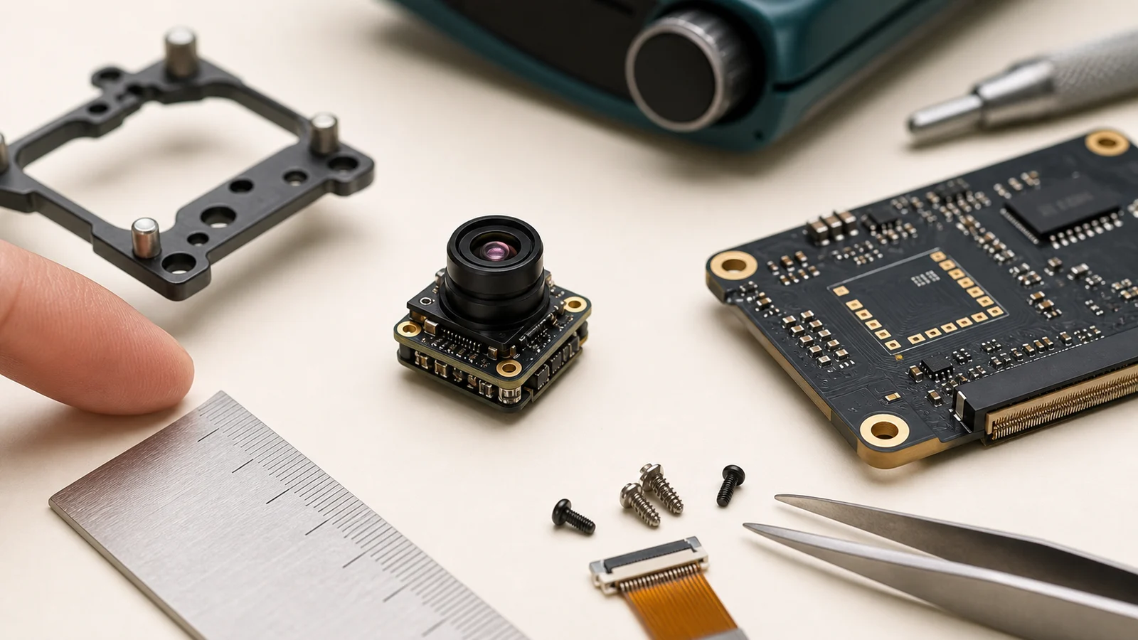
Pixel pitch changes the optical design space. A 640 × 512 array at 12 μm has an active area of 7.680 × 6.144 mm, with a diagonal of about 9.84 mm. At 17 μm, the same pixel count occupies 10.880 × 8.704 mm.
At equal angular FOV, focal length scales with pitch: 12/17 is approximately 0.706, a 29.4% linear reduction. A shorter focal length can help reduce the optical envelope, but no fixed percentage reduction in lens mass or payload inertia follows. Glass type, aperture, element count, barrel design and distance from the rotation axis still matter.
Small LWIR pixels also make diffraction, lens Modulation Transfer Function (MTF) and sensitivity important to assess together. Faster optics can improve light collection and diffraction performance, but F/1.4 or F/1.6 is not an automatic failure threshold. The acceptable F-number depends on the complete optical design and the spatial contrast the application needs. Edmund Optics explains the Airy-disk relationship.
Wafer-Level Packaging (WLP) can reduce detector-package size and support volume assembly. It does not by itself establish a complete camera’s weight, mounting method or connector. For a compact thermal imaging camera, budget the lens, boards and enclosure separately and use the ordered assembly’s documentation.
2. Optical Engineering: Calculating FOV, IFOV, and DRI for Compact Payloads
Select the optical train before freezing the enclosure. Use lenses and protective windows specified for the required LWIR band; check transmission, coatings and environmental durability for the selected materials. Germanium, chalcogenide glass and other infrared materials have different optical and mechanical tradeoffs.
When planning a compact thermal imaging camera with the thermal imaging calculator, begin with the following ideal geometric relationships:
Horizontal Field of View (HFOV) & Vertical Field of View (VFOV):
HFOV = 2 × arctan(W_sensor / (2 × f)) = 2 × arctan((N_H × p) / (2 × f))
VFOV = 2 × arctan(H_sensor / (2 × f)) = 2 × arctan((N_V × p) / (2 × f))
Here N_H and N_V are horizontal and vertical pixel counts, p is pixel pitch, and f is effective focal length. Use the same length units for p and f: 12 μm = 0.012 mm. Convert the arctangent result to degrees when reporting FOV.
Instantaneous Field of View (IFOV), small-angle approximation:
IFOV ≈ p / f radians = 1000 × p / f milliradians (mrad)
For a 640 × 512 array at 12 μm with a 9.1 mm focal length, the active dimensions are 7.680 × 6.144 mm. The ideal model gives approximately 45.76° horizontal FOV, 37.31° vertical FOV and 1.319 mrad IFOV.
At an axial distance of 10 m, this corresponds to approximately 13.19 mm pixel sampling and 8.44 × 6.75 m scene coverage on a plane perpendicular to the optical axis. Actual coverage and spatial measurement performance also depend on lens distortion, focus and viewing geometry. One sampling interval is not a guarantee that an object that small can be resolved or measured accurately.
Geometric example only: the 9.1 mm calculation is not a current AeroMini lens specification. The manufacturer’s AeroMini lens table lists the 9 mm lens at 48.7° × 38.6° H × V, F/1.0. Use its configuration-specific FOV for selection rather than replacing it with the ideal calculation.
Scene coverage and operational range answer different questions. Johnson-style criteria provide approximate image-resolution estimates for detection, recognition and identification under stated assumptions. Target dimensions and contrast, optics, detector noise, atmosphere, motion and image processing also influence performance; pixel count alone does not establish field or algorithm success.
- ✅ Detection: Distinguishing an object of interest from its background without yet determining its class.
- ✅ Recognition: Distinguishing the general target class, such as a person, animal or vehicle, under the specified test conditions.
- ✅ Identification: Resolving the particular features required by the application; define those features and validate them in representative imagery.
On an airborne gimbal, a longer focal length reduces IFOV and increases the target’s pixel coverage, but narrows the field and makes angular jitter more visible. Outdoor selection must also account for enclosure protection. Our outdoor field guide separates finished handheld observation devices from OEM modules for your own enclosure and host; it does not qualify a module as a ready airborne payload.
3. SWaP Optimization: Thermal Dissipation, Mass Budgets, and UAV Dynamics
Size, Weight, and Power (SWaP) budgets link the camera to the rest of the platform. Embedded devices often prioritize runtime, board space and heat near the processor. UAV payloads add balance, cable movement and vibration requirements. Assess these together rather than choosing a core from its smallest headline dimension.
1. Thermal Equilibrium and Sensor Drift: Internal temperature changes and thermal gradients can affect microbolometer response and image uniformity. Plan a controlled heat path and evaluate warm-up, steady operation and changing ambient conditions in the final enclosure. Keep nearby processor and motor-driver heat in the thermal model.
A typical power figure below 0.5 W does not guarantee negligible drift or a particular shutter interval. Shutter-based correction may briefly interrupt imagery, with behavior depending on the module, firmware and operating conditions. Verify the settings and any interruption with the tracking or measurement workflow; FLIR’s shutter/FFC explanation provides useful general background.
2. Mass Distribution and Gimbal Dynamics: Include the lens, flange, interface board, cable, fasteners and protective housing in the mass budget. Their positions relative to the gimbal axes determine balance and rotational inertia. A low core weight helps the starting budget but does not establish motor torque, control-loop bandwidth or platform stability.
Athermalized optics are designed to reduce focus changes over a specified temperature range. Confirm that range for the selected lens and test focus across the complete assembly’s required conditions. A camera’s operating-temperature range is not automatically a guarantee of constant optical focus across that range.
3. Vibration Damping and Mechanical Rigidity: Establish the expected vibration and shock environment for the actual UAV, robot or tool. Use the manufacturer’s mounting points, torque limits and approved retention methods, and strain-relieve cables. Check connector retention, lens support and image quality under representative loads instead of applying one generic vibration spectrum or threadlocker recipe.
For a compact thermal imaging camera replacing an existing core, recheck the thermal path, center of gravity, connector clearance and host timing even if its footprint is smaller. The LWIR thermal camera OEM retrofit memo provides a related planning path.
4. Embedded Interface Protocols: MIPI CSI-2, SPI, USB, and BT.656 Direct Capture
Connect the camera to the host by matching the delivered pixel format, data rate, control channel and electrical levels. A familiar interface name does not guarantee compatible drivers, radiometry or low latency.
MIPI CSI-2: This interface can carry high-bandwidth image data to compatible host receivers. Confirm lane count, pixel packing, timing and control, plus the host driver and capture path. Bit depth, radiometry, frame rate and end-to-end latency depend on the camera and implementation. The MIPI CSI-2 specification overview describes the transport, not a promise of plug-and-play V4L2 integration on every SoC.
SPI: A low-pin-count SPI path can suit lower-resolution thermal sensing on an MCU. Check the selected module’s clock limits, packet format, frame rate, connector, logic levels and total power. These are not defined by SPI itself, and an MCU still needs sufficient memory and processing time for the chosen acquisition mode.
USB: USB can simplify bench evaluation when the module and host support matching UVC formats. Control may use CDC/ACM or a vendor-specific interface. Verify which stream carries images or temperature data and whether the ordered camera is radiometric; CDC is not a universal temperature-data channel.
The USB-IF UVC specification set defines a video class, not a thermal data contract. Even a 16-bit grayscale container does not by itself prove that calibrated temperatures are available.
Parallel Digital (BT.656 / DVP): Parallel video can suit an FPGA or compatible host capture interface. Confirm pixel format, sync timing, clock and I/O voltage. DVP is a general description of a parallel interface, not a synonym for BT.656; conventional SD BT.656 timing should not be assumed for every thermal data stream.
Analog CVBS: CVBS supports compatible PAL/NTSC video chains and legacy displays. Total latency still includes sensor readout, image processing, conversion and display behavior. Analog transport does not guarantee zero camera or system latency.
| Bus Protocol | Frame Rate / Timing | Bandwidth Profile | Host Requirements | Primary Application Fit |
|---|---|---|---|---|
| MIPI CSI-2 | Module and mode dependent | Lane count, lane rate and packing dependent | Compatible SoC camera receiver | Embedded vision; validate receiver and driver |
| SPI | Module and mode dependent | Clock and protocol dependent | MCU with matching SPI and memory budget | Lower-resolution sensing; verify full module power |
| USB | Module and mode dependent | USB 2.0 High-Speed: nominal 480 Mbit/s signalling; usable payload is lower | PC or SBC with matching class/vendor support | Evaluation, portable tools and supported capture |
| BT.656 / DVP | Output timing dependent | Conventional SD BT.656 example: 27 MHz; other DVP modes vary | Compatible FPGA, DSP or parallel capture input | Custom capture with verified sync and format |
| CVBS (PAL/NTSC) | PAL: 50 fields/s (25 frames/s); NTSC: about 59.94 fields/s (29.97 frames/s) | Analog baseband; field rate is not full-frame capture rate | Compatible analog receiver / monitor | Legacy video chains; measure total latency |
As a payload calculation, 640 × 512 × 16 bits × 60 frames/s is about 314.6 Mbit/s before overhead. A 160 × 120 × 16-bit stream at an assumed 25 frames/s is 7.68 Mbit/s. These arithmetic examples explain different host burdens; they do not establish a product’s supported frame rate or bus throughput.
5. Product Benchmarking: High-Resolution Imaging vs. Low-Power Sensing
The central choice is still high-resolution imaging versus lower-resolution sensing with a tighter power and compute budget. The current AeroMini and SuperMini paths below both use 640 × 512 detectors. They represent different integration packages within that high-resolution category, rather than a substitute for every milliwatt-scale sensor.
CAMCUDA AeroMini 640: selected lens and interface-board assembly
The current AeroMini product page specifies a 640 × 512 VOx detector with 12 μm pixels. Non-radiometric imaging ships at 60 Hz by default, with a 30 Hz factory option. The separate 25 Hz radiometric version is enquiry-only; its documented lenses are 9, 13 and 18 mm.
The 21 × 21 × 28 mm dimensions and <20 g weight exclude the lens and flange. Typical module power is <0.5 W at 25 °C; complete-kit consumption can differ. Confirm the full lens, board and cable envelope for your compact thermal imaging camera.
| Parameter | Current AeroMini product-page specification / configuration boundary |
|---|---|
| Detector / resolution | Uncooled VOx; 640 × 512 |
| Pixel pitch / spectral response | 12 μm; 8–14 μm |
| Frame rate / camera version | Non-radiometric: 60 Hz default, 30 Hz factory option. Radiometric: 25 Hz, enquiry-only. |
| NETD | ≤30 mK at 25 °C, F/1.0, as listed on the current product page |
| F-number / polarity | F/1.0; White hot / Black hot |
| Supply / board boundary | Family table lists 5 V or 12 V by board. Illustrated 16/26-pin POWER_IN1 / POWER_IN2 are 5 V inputs only; never apply 12 V to those pins. |
| Typical power | <0.5 W at 25 °C for the module; complete-kit consumption may differ |
| Interface packages | USB + CVBS + MIPI tailboard or separate Type-C + CVBS tailboard; both-board package also listed |
| Video / control scope | YUV, USB, BT.656 and CVBS/PAL/NTSC depend on board and firmware. UART / RS232 / RS422 are family-level, board-dependent entries. |
| Illustrated serial connector | 16-pin USB/CVBS reference identifies RS232; it does not establish RS422 on that connector |
| Dimensions / weight | 21 × 21 × 28 mm; <20 g, excluding lens and flange |
| Radiometric range / lenses | −20 °C to +550 °C; 9 / 13 / 18 mm, radiometric version only. Confirm accuracy, data format and interface. |
| Operating / storage temperature | −40 °C to +80 °C / −50 °C to +85 °C |
| Humidity | 5–95%, non-condensing |
Lens-table references: the current AeroMini page lists 7 mm at 64° × 52°, 9 mm at 48.7° × 38.6° and 18 mm at 24.2° × 19.5° H × V. Online non-radiometric lens choices are 4, 7, 9, 13, 18, 25, 35 and 50 mm; 15, 60 and 75 mm entries are enquiry references. Confirm the chosen configuration and current availability.
Document boundary: the integrated AeroMini PDF remains useful for its lens and interface references. Request the matched specification and interface-board revision when freezing an order.
CAMCUDA SuperMini 640 / 640T: separate bare-core comparison
The SuperMini 640 / 640T product page describes a smaller 8 μm-pitch 640 × 512 core. Choose SuperMini 640 for 50 Hz imaging without temperature measurement, or SuperMini 640T for 30 Hz thermography. Its core footprint is smaller than AeroMini’s published module envelope, but compare complete assemblies before drawing payload-size or weight conclusions.
| Parameter | SuperMini 640 / 640T specification / configuration boundary |
|---|---|
| Detector / resolution / pitch | Uncooled VOx; 640 × 512; 8 μm; 8–14 μm |
| Model / frame rate | SuperMini 640: imaging only, 50 Hz. SuperMini 640T: thermography, 30 Hz. |
| NETD | ≤40 mK at 25 °C, F1.0 |
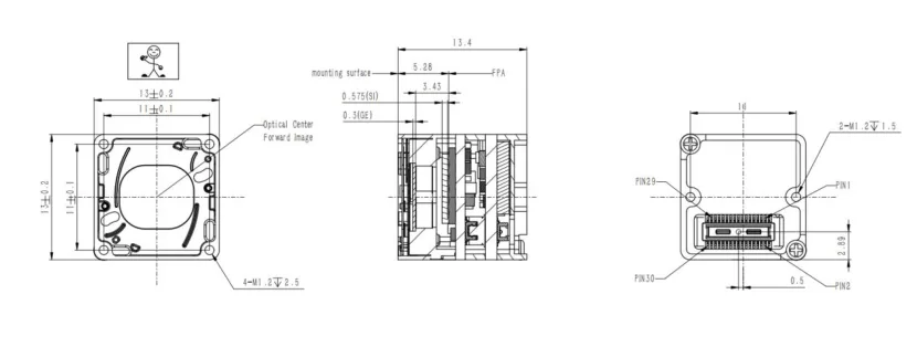
| Bare-core dimensions / weight | 13 × 13 × 13.4 mm; <3.5 g, excluding optics and boards |
| Typical core power | ≤0.5 W at 25 °C, excluding expansion board |
| Core connector / supplies | Hirose DF40C-30DP-0.4V(51), 30 pins. MAIN_POWER 3.8–5.2 V, +3.3 V rail 3.28–3.32 V, +1.8 V rail 1.78–1.82 V; follow all rail and sequencing requirements. |
| Video / control | 8-bit LVCMOS and 2-lane MIPI paths; 640 BT656 / 640T CDS3. BT656 and MIPI cannot operate simultaneously. UART uses 1.8 V logic. |
| USB / analog integration | USB 2.0 pins; optional TMS6102V100F022 4-pin USB expansion board. Bare-core CVBS requires an external video-buffer IC. |
| 640T thermography only | −20 °C to +150 °C and 100 °C to +650 °C ranges. Confirm mode, calibration and temperature-data parsing for the ordered configuration. |
| Operating conditions | Operating: −40 °C to +70 °C; thermography: −20 °C to +60 °C. Storage: −45 °C to +80 °C. Humidity: 5–95%, non-condensing. |
Published F1.0 athermal lens options are 3.7, 6.1, 8.7 and 11 mm. The manufacturer’s 6.1 mm entry is 46.6° × 37.6° H × V. The SuperMini Product Manual V1.0.0 defines the core interfaces and mechanical reference; obtain the drawing for the selected lens and expansion board before enclosure design.
Low-resolution, low-power sensing remains a separate path
For a remote occupancy sensor, appliance or localized heat map, a lower-resolution array may reduce data volume, memory needs and host processing. Set the required target size, scene coverage, update rate and temperature-measurement capability first. A 160 × 120, 16-bit image alone occupies 38,400 bytes, compared with 655,360 bytes for 640 × 512, before extra buffers or metadata.
Then compare active power, sleep current, wake-up time, duty cycle, supply rails and the complete host-and-sensor budget. Check whether a candidate provides calibrated temperatures or only image values, and whether its interface can deliver the required updates within the MCU’s timing and memory limits. Lower resolution alone does not establish lower total system power or adequate sensing performance.
Neither current 640 option above is specified as a 76 mW SPI replacement. Do not carry an older micro-array’s power, single-rail supply, FPC connector or frame-rate claims into an AeroMini or SuperMini design. If milliwatt-scale operation is essential, request a currently documented low-power candidate and assess it separately.
For a finished handheld observation device rather than an OEM build, the field observation devices catalog is a separate product path. Its listings do not establish integration readiness for a custom UAV or fixed-site enclosure.
6. Mechanical, Power Sequencing, and Radiometric Calibration Integration
Moving a compact thermal imaging camera from an evaluation kit into a product requires mechanical, electrical and software evidence for the same configuration. Record the model, lens, board, firmware and document revision together.
1. Low-noise power design and sequencing
Use the ordered module’s voltage, ripple, current, decoupling and sequencing requirements. Evaluate regulator noise and transient response at the actual load and disturbance frequencies; an external LDO or a single PSRR number is not a universal solution. TI’s regulator-noise and PSRR discussion explains why frequency, load and headroom matter.
For AeroMini’s illustrated USB + CVBS + MIPI board, POWER_IN1 on the 16-pin reference and POWER_IN2 on the 26-pin reference are 5 V inputs only. The family-level 12 V entry does not authorize 12 V on either pin. The separate Type-C + CVBS board needs its own matched guide.

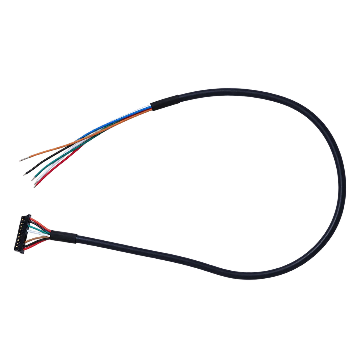
The SuperMini bare core requires multiple rails, a 1.8 V UART interface and the full manual’s power-on sequence. Its CVBS output requires an external video-buffer IC. Expansion-board inputs have their own definitions; they must not be applied to the bare-core connector. See manual PDF page 8 for power requirements.
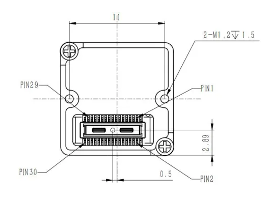
2. High-speed routing, capture and mechanical fit
Follow both the camera and host PHY layout guides for differential impedance, skew, termination and return paths. A generic 100 Ω or 0.15 mm rule is not a substitute for the actual interface requirements. Validate the cable and connector as part of the link, particularly near switching supplies or motor wiring.
For a separately selected SPI sensor, choose any source-series termination from the driver, interconnect and timing requirements. Place it near the signal’s driver: the host normally drives SCK and MOSI, while the camera drives MISO. One resistor value placed at every MCU pin is not a universal recipe; TI’s hardware guidance provides system-dependent termination examples.
For software bring-up, use the AeroMini Linux drivers, examples and SDK FAQ to locate its matched resources. Confirm the host, firmware, format and frame rate before integration; a listed SDK is not evidence that your target platform has been tested. SuperMini has its own manual and interface definitions; the AeroMini SDK must not be presented as compatible.
The reviewed AeroMini integrated PDF has no dimensioned full-assembly drawing. Request CAD for the selected lens and board. Its separately referenced 7 mm STEP model is not a universal assembly drawing. SuperMini’s bare-core figure and its separate 6.1 mm assembly drawing serve different scopes and cannot substitute for AeroMini fit evidence.
3. Radiometric calibration and shutter behavior
Non-Uniformity Correction (NUC) addresses pixel-response non-uniformity. Shutter-based Flat-Field Correction (FFC) can update offsets and briefly interrupt live imagery. Shutterless methods and their operating limits are module-specific; do not assume scene-based correction alone guarantees uninterrupted, accurate thermography.
- ⚙️ Correction behavior: Confirm warm-up, correction triggers, manual controls and the actual effect on recorded frames in the intended enclosure and ambient transitions.
- ⚙️ Sensitivity versus accuracy: NETD describes sensitivity under stated test conditions. Absolute temperature accuracy requires a radiometric configuration, valid calibration and appropriate emissivity, reflected-temperature and optical-path settings.
- ⚙️ Data interpretation: Some products output already calibrated temperature data; others require a documented conversion. Match the format and mode to the selected model. SuperMini 640T CDS3/temperature handling does not apply to the imaging-only 640, and an arbitrary 14- or 16-bit image is not a temperature map.
FLIR’s radiometry setup guide offers general background on environmental and infrared-window compensation. Apply the selected CAMCUDA configuration’s own measurement limits and calibration instructions.
7. Deep-Dive OEM Integration FAQ
Why do budget compact thermal cameras struggle with range and clarity compared to dedicated OEM cores?
Price category alone does not determine image quality. Native resolution, lens FOV and MTF, NETD, frame rate and processing all affect what an image can show. Interpolation can enlarge a display image but does not add independently measured detector samples; low-resolution cameras can still suit localized sensing.
At a matched FOV, more native samples can place more pixels across a target. IFOV itself depends on pixel pitch divided by focal length, so higher pixel count alone does not guarantee a smaller IFOV. For a compact thermal imaging camera, validate the required detail with the selected lens and operating conditions.
The current AeroMini page specifies 640 × 512, 12 μm and NETD ≤30 mK at 25 °C, F/1.0. Its 60/30 Hz imaging and 25 Hz enquiry-only radiometric versions are distinct; these specifications do not by themselves guarantee a DRI range.
Can a compact thermal camera module integrate directly with embedded MCU/MPU platforms without bridge boards?
Sometimes, but only when the module’s electrical levels, data format and timing match the host and suitable capture software is available. Check power rails, connector orientation, control logic and buffering before deciding whether a bridge or expansion board can be omitted.
A separately documented low-resolution SPI sensor can be appropriate for an MCU with enough memory and bandwidth. AeroMini and SuperMini are not established here as SPI micro-array replacements. AeroMini’s USB + CVBS + MIPI and Type-C + CVBS boards require different wiring references; SuperMini uses a multi-rail 30-pin core interface with 1.8 V UART and an external CVBS buffer.
MIPI support does not establish direct V4L2 compatibility, radiometry or a latency target. Use the AeroMini SDK FAQ or the SuperMini interface manual for the correct family, then validate the chosen host and firmware. SuperMini 640T CDS3 and temperature-data parsing also need configuration-specific implementation.
What SWaP parameters matter most when selecting a compact thermal camera for UAV payloads or handheld tools?
Start with the complete system envelope, heat path and power budget, then validate the host link and mechanical environment. Three checks matter for a compact thermal imaging camera:
1. Envelope and mass distribution: Include the optical assembly, board, cable and enclosure. AeroMini’s 21 × 21 × 28 mm / <20 g excludes lens and flange; SuperMini’s 13 × 13 × 13.4 mm / <3.5 g excludes optics and boards. Neither is a complete payload figure.
2. Power and thermal behavior: AeroMini’s typical <0.5 W is a module value at 25 °C; SuperMini’s typical ≤0.5 W excludes its expansion board at 25 °C. Budget startup, accessories and the host, and check warm-up, drift and correction behavior in the final enclosure.
3. Electrical and mechanical compatibility: Match the actual supply rails and sequencing, signal levels and connector. Check lens-specific focus limits and documented shock/vibration conditions. An athermal lens or small core does not by itself guarantee stable focus, gimbal control or elimination of external power circuitry.
📚 References & Further Reading
- Current product specification: CAMCUDA AeroMini 640; integrated PDF and matched developer-resource FAQ.
- Current product and manual: CAMCUDA SuperMini 640 / 640T; Product Manual V1.0.0.
- Manufacturer reference: Teledyne DALSA Infrared Detectors; LYNRED ATTO640-02 datasheet, with stated detector-package and range-estimate assumptions.
- Interface specifications: MIPI CSI-2 overview; USB-IF UVC documents; ITU-R BT.656.
- Video timing reference: Analog Devices: Basics of Analog Video, for the distinction between fields and frames.
- Related guide: Outdoor Field Thermal Imaging Applications; LWIR Thermal Camera OEM Retrofit Engineering Memo.
- Finished observation products: Field Observation Devices Directory; HIKMICRO manufacturer reference.
Technical author: Daniel · Hardware Support
Sales contributors: Vivian, Lena and Sophie