Thermal CCTV Camera Integration Guide: Optics, Interfaces, and OEM LWIR Cores
Thermal CCTV Camera Integration Guide: Optics, Interfaces, and OEM LWIR Cores
When you are designing perimeter security, border surveillance, or critical infrastructure monitoring for the real world, standard optical daylight cameras hit a hard wall fast. The moment you run into zero-lux pitch black, dense industrial smoke, blowing dust, thick sea fog, or targets wearing optical camouflage, standard visual sensors are blind. Integrating an uncooled Long-Wave Infrared (LWIR) thermal cctv camera into your system bypasses these physical limitations entirely. Thermal imagers do not care about reflected light. Instead, they passively measure the raw blackbody thermal radiation emitted by every object in the 8–14 µm spectral band, converting microscopic temperature deltas and emissivity variations into clear, high-contrast imagery day or night.
Here’s the deal: moving from benchtop visible sensors to LWIR imaging is a completely different engineering discipline. You cannot just swap out a CMOS sensor for a microbolometer and call it a day. Building a rugged, high-performance thermal camera or dropping an OEM core into an existing housing requires balancing sensor physics, optical throughput, embedded compute pipelines, and mechanical heat dissipation. If you mess up your instantaneous field of view calculations or neglect thermal drift on your carrier board, your system will either drop frames, throw false alarms, or lose target focus the second the sun beats down on the chassis.
In the shop, we see teams run into the same roadblocks time and again. They struggle to bridge bare sensor outputs like MIPI CSI-2 or USB UVC into clean ONVIF Profile S/T video streams, miscalculate Johnson criteria ranges for human targets, or mount protective Germanium windows incorrectly and end up with terrible Narcissus ghost reflections right in the middle of their frame. This technical guide breaks down the electro-optical physics, lens materials, video interface bridging, and optomechanical requirements you need to design, build, and deploy an enterprise-grade thermal CCTV camera system.
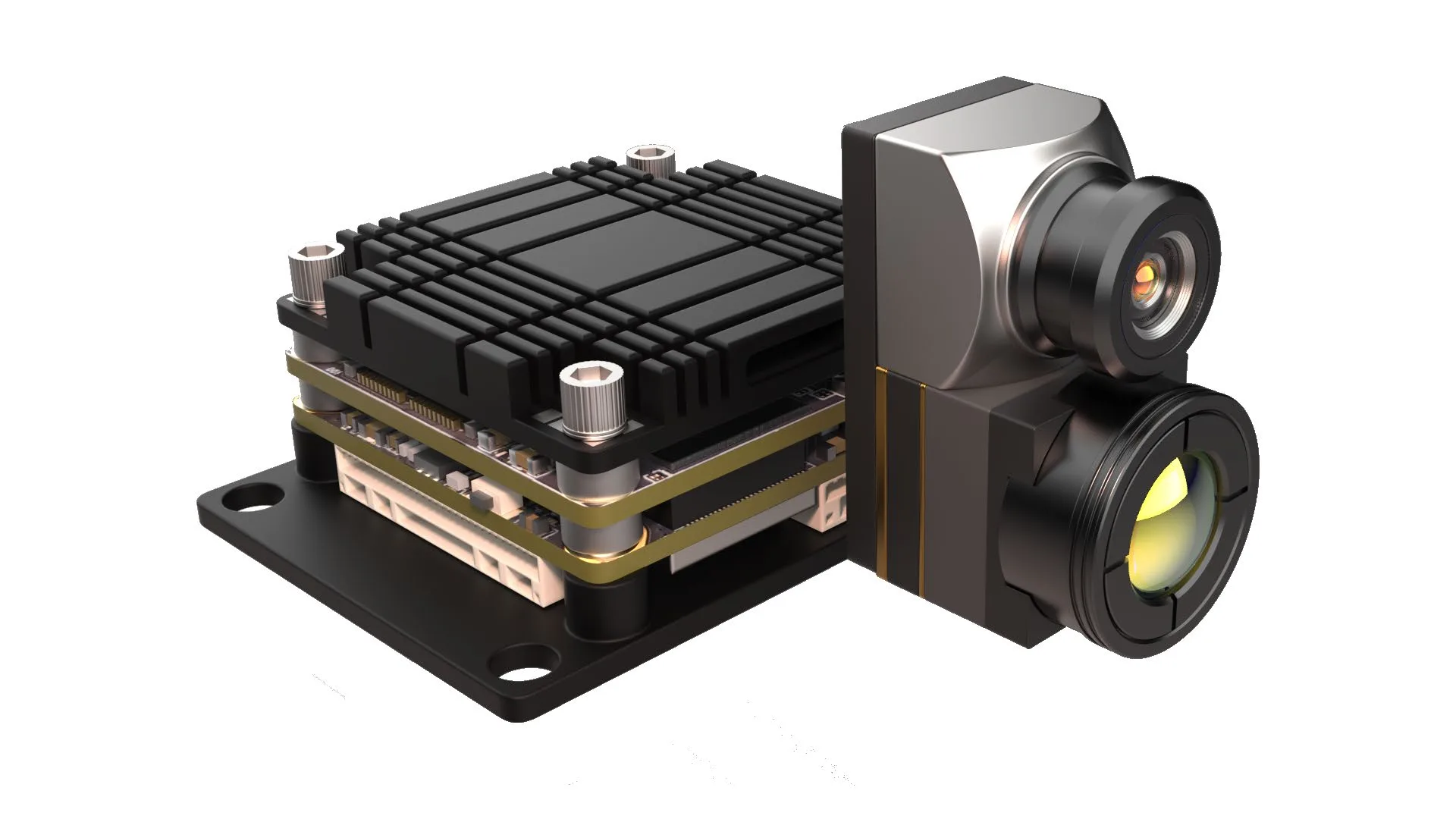
Table of Contents
- 👉 1. Thermal CCTV Camera Physics vs. Visible Light CCTV
- 👉 2. Optics, Instantaneous FOV, and DRI Range Calculations
- 👉 3. Embedded Interface Architecture: MIPI, USB UVC, SPI, and IP/ONVIF Bridging
- 👉 4. Real OEM LWIR Core Comparison: 640×512 vs. 160×120 Modules
- 👉 5. Optomechanical Integration, Protective Windows, and Thermal Dissipation
- 👉 6. Deep-Dive Engineering FAQ
1. Thermal CCTV Camera Physics vs. Visible Light CCTV
To design an uncooled thermal cctv camera that actually delivers in field conditions, you need to step away from standard visible-light silicon thinking. Standard CMOS/CCD imagers operate in the narrow visual band from 0.4 µm to 0.7 µm, or push slightly into Near-Infrared (NIR) territory at 0.85 µm to 0.94 µm using active LED illuminators. These visible sensors are 100% dependent on photon reflection. If an intruder stands in front of a dark backdrop with no active illumination, or if particulate smoke scatters visible wavelengths, the sensor produces nothing but flat noise floor.
Thermal imagers operate on an entirely different physical domain: the Long-Wave Infrared (LWIR) band between 8.0 µm and 14.0 µm. Every physical object in the universe sitting above absolute zero (-273.15 °C or 0 Kelvin) radiates electromagnetic energy naturally. According to Wien’s Displacement Law, terrestrial targets like humans, vehicles, and machinery sitting between -40 °C and +100 °C emit peak radiant energy right in the sweet spot between 9.3 µm and 10.5 µm. That means your scene is literally glowing with its own thermal signature.
The total radiant power leaving that target surface is governed by the classic Stefan-Boltzmann Law:
j* = ε · σ · T⁴
Where j* is total radiant emittance (W/m²), ε is the surface emissivity (from 0 for a polished mirror up to 1.0 for a true blackbody), σ is the Stefan-Boltzmann constant (5.670374 × 10⁻⁸ W/m²·K⁴), and T is absolute temperature in Kelvin. Look closely at that fourth-power exponent (T⁴). That steep exponential curve means even a fraction-of-a-degree delta between a human body (37 °C) and a cool ambient background (15 °C) creates an massive difference in radiated flux, popping the target out from background clutter effortlessly.
Uncooled Microbolometer Operation and VOx Thin Films
Military-grade cryocooled Mid-Wave Infrared (MWIR) cameras use Stirling cycle coolers to drop focal plane temperatures down to 77 Kelvin (-196 °C). They offer extreme standoff ranges, but the mechanical pumps burn power, generate vibration, cost tens of thousands of dollars, and wear out after roughly 10,000 to 15,000 hours of run time. For 24/7 industrial and perimeter security CCTV, we rely exclusively on uncooled microbolometer Focal Plane Arrays (FPAs) that operate reliably across wide ambient temperatures (-20 °C to +60 °C or higher) with zero moving cryogenic parts.
A modern microbolometer array is an absolute marvel of micro-electro-mechanical systems (MEMS) engineering. Each individual pixel is a microscopic membrane suspended a couple of microns above an underlying silicon Readout Integrated Circuit (ROIC) by tiny, micro-machined thermal isolation legs. Each membrane contains an infrared absorption layer and a thin film of thermistor material with a steep Temperature Coefficient of Resistance (TCR). In commercial production, Vanadium Oxide (VOx) is the undisputed champion over Amorphous Silicon (α-Si). VOx delivers a much higher TCR (around -2% to -3% per Kelvin), generates substantially lower 1/f flicker noise, and stays rock-solid over broad thermal swings.
When incoming LWIR energy passes through your Germanium lens and hits that suspended VOx membrane, the membrane absorbs the thermal flux and heats up. This micro-temperature change alters the membrane’s electrical resistance. The ROIC reads this resistance change across every pixel on the grid, multiplexes the signals, and feeds them into high-precision on-chip ADCs, handing your video pipeline a clean 14-bit or 16-bit digital radiometric thermal matrix.
Key Detector Metrics: NETD, NUC, and Pixel Pitch
When you are sourcing thermal cores on the test bench, cut through the marketing sheets and focus on these three core hardware metrics:
- ⚙️ Noise Equivalent Temperature Difference (NETD): Measured in millikelvins (mK), NETD is the ultimate signal-to-noise metric for a thermal core. It tells you the absolute smallest temperature difference the sensor can pull out of its own noise floor. A top-tier uncooled VOx core achieves NETD ≤ 30 mK at an F/1.0 aperture, meaning it can cleanly distinguish temperature deltas as tiny as 0.03 °C. High sensitivity is what keeps your image crisp during thermal washouts, like when a sudden downpour equalizes target and background temperatures.
- ⚙️ Non-Uniformity Correction (NUC): No two microbolometer pixels come off the wafer identical; each has tiny variations in baseline resistance and thermal gain. Without real-time compensation, your image will turn into a noisy, fixed-pattern mess. OEM cores fix this by running automatic NUC cycles, dropping an internal flat-temperature shutter blade across the sensor plane for a split second to re-zero pixel offsets, or by using continuous shutterless algorithmic motion estimation.
- ⚙️ Pixel Pitch (Microns): This is the center-to-center distance between adjacent pixels on the FPA. Older cores ran on chunky 25 µm or 17 µm pitches, but modern industrial cores standardly use a 12 µm pitch. Shrinking the pixel pitch packs more resolution onto a smaller silicon die. That allows your optical engineers to use shorter focal length Germanium lenses to hit the exact same optical magnification and standoff range, saving massive amounts of system weight and lens cost.
2. Optics, Instantaneous FOV, and DRI Range Calculations
Here is a basic rule of optical engineering: standard optical glass (like BK7 or fused silica) is an impenetrable brick wall to LWIR radiation. Standard glass reflects and absorbs everything between 8 µm and 14 µm. If you stick a standard optical glass lens or dome in front of a microbolometer, your sensor will see nothing but the thermal reflection of the camera’s own internal housing. You have to use specialized, exotic infrared-transmitting materials:
- ⚙️ Germanium (Ge): The absolute gold standard for high-performance thermal optics. Germanium has a massive refractive index (~4.0 at 10 µm), which allows optical designers to create compact, highly corrected, low-aberration lenses. The catch? Raw Germanium experiences thermal runaway at temperatures above 70 °C (it turns opaque as free electrons jump the bandgap) and it scratches easily without protective hard coatings.
- ⚙️ Chalcogenide Glass (e.g., GASIR): Synthetic amorphous glasses that offer exceptionally stable refractive indices across extreme temperatures. Chalcogenide is ideal for precision molded optics and true athermalized optical barrel designs that stay razor-sharp from -40 °C all the way to +80 °C without requiring motorized refocusing.
- ⚙️ Zinc Selenide (ZnSe) & Zinc Sulfide (ZnS): Excellent materials primarily selected for specialized multispectral optical windows or multi-element color-corrected infrared lens assemblies.
Every external optical element exposed to the elements needs a broadband Anti-Reflective (AR) optical coating on inner surfaces to keep transmission above 92%, combined with an external Diamond-Like Carbon (DLC) hard coating. DLC coatings are non-negotiable for industrial CCTV; they protect the expensive Germanium substrate from blowing sand abrasion, acid rain, salt spray, and corrosive refinery chemicals.
Instantaneous Field of View (IFOV) Geometry
Field of view and spatial sampling resolution come down to the interplay between your detector pixel pitch and lens focal length. The parameter you must calculate before ordering optics is the Instantaneous Field of View (IFOV), expressed in milliradians (mrad):
IFOV (mrad) = [Pixel Pitch (µm) / Focal Length (mm)] = d / f
Once you know the IFOV, calculating the physical ground footprint covered by a single pixel at any operational distance is straightforward:
Spot Size on Target (m) = IFOV (mrad) × Distance (km)
Let’s look at real-world numbers: take a high-density 12 µm core paired with a wide-angle 4.9 mm lens. That setup gives you an IFOV of 2.45 mrad, projecting a single pixel footprint of 2.45 meters at a distance of 1 kilometer. That is ideal for wide-area situational awareness and close-in perimeter gates. If you swap that lens for a 35 mm telephoto optic, your IFOV tightens down to 0.34 mrad. Now your single pixel footprint at 1 kilometer is just 0.34 meters, concentrating dozens of spatial pixels on distant human and vehicle targets for reliable long-range identification.
Johnson’s DRI Criteria in Security Engineering
To spec standoff distances properly, the surveillance industry relies on the classic Johnson Criteria. This framework defines the minimum number of resolved spatial line pairs (cycles) needed across a target’s critical dimension (standardized at 1.8 m height × 0.5 m width for a human, and 2.3 m × 2.3 m for a vehicle) to execute specific security tasks:
- ✅ Detection (1.5 line pairs / ~3 pixels on target): The operator or automated analytics engine can verify that an anomalous hot object is present against background thermal clutter.
- ✅ Recognition (6.0 line pairs / ~12 pixels on target): You can classify the target into a broad category—telling a walking human from a stray deer, or a standard sedan from a flatbed utility truck.
- ✅ Identification (12.0 line pairs / ~24 pixels on target): High-confidence verification of target attributes, such as confirming whether a trespasser is carrying tools or weapons, or identifying a specific utility truck model.
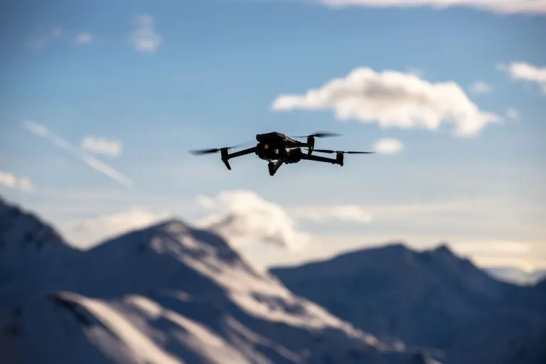
When you are designing combined ground-air perimeter surveillance architectures that link static thermal CCTV towers with airborne patrols, sourcing standardized optical packages from dedicated systems like a 640×512 UAV thermal imaging camera or modular drone camera payload ensures seamless target handoffs, cross-cueing, and identical coordinate mapping across your entire sensor grid.
3. Embedded Interface Architecture: MIPI, USB UVC, SPI, and IP/ONVIF Bridging
Here is where many teams hit a snag: bare OEM thermal camera cores output raw digital or analog frames directly from the ROIC processing block. They do not ship with an RJ45 Ethernet jack or an embedded RTSP streaming server built-in. Building a true IP thermal camera requires selecting the right low-level interface and routing it to an embedded System-on-Chip (SoC) carrier board.
Hardware Video Interface Protocols
- ⚙️ MIPI CSI-2 (Camera Serial Interface): The absolute standard for high-speed embedded designs. MIPI CSI-2 uses multi-lane differential signaling to stream uncompressed 14-bit or 16-bit raw radiometric data directly into the Image Signal Processor (ISP) or Video Processing Unit (VPU) of modern SoCs (like the Rockchip RK3588, NXP i.MX8, or NVIDIA Jetson). It introduces near-zero bus latency, making it the premier choice for edge AI video pipelines.
- ⚙️ USB Video Class (UVC): A plug-and-play USB interface that encapsulates thermal frames into standard UVC descriptors. USB UVC thermal cores let you plug straight into x86 industrial box PCs, Linux single-board computers, or Android gateways without writing custom kernel drivers.
- ⚙️ CVBS (Composite Video Baseband Signal): Legacy 75 Ω analog composite output (PAL/NTSC). CVBS offers ultra-low latency (<20 ms) video transmission over standard coaxial cables, making it rock-solid for direct monitor connections and legacy matrix systems.
- ⚙️ SPI (Serial Peripheral Interface): A synchronous serial link utilized on low-power, small-array thermal modules (like 160×120 sensors). SPI transfers packetized radiometric frames alongside command registers for gain switching and sensor calibration.
Bridging to Network Video Recorders (NVR) and VMS Platforms
To convert an OEM microbolometer feed into an enterprise IP stream that any Milestone, Genetec, or standard NVR can ingest, your Linux carrier board firmware needs to run the following processing pipeline:
- ⚙️ Step 1: Radiometric Ingestion & Defective Pixel Correction: The SoC captures the raw 14-bit digital stream over MIPI or USB, maps out hot/dead pixels in real time using neighbor interpolation, and applies baseline two-point NUC offset matrices.
- ⚙️ Step 2: Dynamic Range Compression & Tone Mapping: A raw 14-bit thermal image contains 16,384 discrete levels of thermal intensity, but standard security monitors only display 8-bit video (256 grayscale levels). The embedded pipeline must execute advanced tone mapping—such as Contrast Limited Adaptive Histogram Equalization (CLAHE) or Digital Detail Enhancement (DDE). These algorithms compress high-dynamic-range scenes while actively boosting fine thermal gradients on human and vehicular targets.
- ⚙️ Step 3: Hardware Video Compression: The enhanced 8-bit YUV/RGB frames pass into the SoC’s hardware VPU, compressing the video into high-efficiency H.264 (AVC) or H.265 (HEVC) streams at targeted bitrates.
- ⚙️ Step 4: RTSP Pipeline & ONVIF Daemon: The compressed stream is wrapped inside an RTSP/RTP multimedia server (using GStreamer or Live555). Concurrently, an embedded ONVIF Profile S (basic streaming) and Profile T (advanced streaming and analytics event metadata) daemon runs in user space. This enables auto-discovery, PTZ commands, and motion alarm integration across all enterprise VMS platforms.
Edge AI and Analytics Integration
Running computer vision engines like OpenCV directly on your embedded carrier board changes the game for site automation. Visible daylight cameras are notorious for false alarms triggered by headlights, passing cloud shadows, windblown trees, or moths swarming near illuminators. Thermal imaging isolates targets purely by surface heat contrast, rendering analytics immune to visual lighting tricks. Running modern deep learning models directly on localized Wikipedia – Edge Computing hardware lets your thermal camera autonomously execute target classification, intrusion tripwire alerts, perimeter loitering tracking, and critical temperature alarms directly on the edge node.
For carrier board pinouts, embedded Linux SDKs, and hardware timing diagrams, hardware engineers can pull reference schematics and firmware directly from the manufacturer’s central technical support portal.
4. Real OEM LWIR Core Comparison: 640×512 vs. 160×120 Modules
Choosing the right OEM thermal engine comes down to your operating envelope, size, weight, and power (SWaP) limits, and the required target classification distance. Below, we compare two battle-tested OEM LWIR camera modules designed for different integration tiers: the flagship high-resolution CAMCUDA FlexMini 640 and the ultra-low-power embedded CAMCUDA TC160-NF.
Product Showcase 1: CAMCUDA FlexMini 640 LWIR Thermal Camera Module
The CAMCUDA FlexMini 640 is an uncooled VOx thermal imaging engine purpose-built for enterprise perimeter CCTV cameras, heavy-duty Pan-Tilt-Zoom (PTZ) positioning heads, UAV gimbals, and tactical surveillance appliances. Featuring a 640 × 512 focal plane array with a tight 12 µm pixel pitch, it delivers high spatial resolution, low thermal noise (NETD ≤ 30 mK), and fluid 50 Hz real-time output in an ultra-compact 23.1 g package.

Key Hardware Specifications (CAMCUDA FlexMini 640)
| Parameter | Technical Specification |
|---|---|
| Detector Architecture | Uncooled VOx (Vanadium Oxide) Focal-Plane Array |
| Thermal Resolution | 640 × 512 pixels |
| Pixel Pitch | 12 µm |
| Spectral Sensitivity | 8 to 14 µm (LWIR) |
| Thermal Sensitivity (NETD) | ≤30 mK reference (@ F1.0, 25 °C) |
| Frame Rate | 50 Hz (PAL reference output) |
| Lens Optical Aperture | F1.0 |
| Video / Host Interfaces | CVBS (Analog), USB UVC, or MIPI |
| Operating Voltage Input | 5 to 24 V DC (Wide-voltage architecture) |
| Power Consumption | <0.7 W reference consumption |
| Total Core Module Weight | 23.1 g |
| Image Latency & NUC | <20 ms reference delay; automatic NUC calibration |
| Operating Temperature Range | -20 °C to +60 °C |
| Interface Pinout Configurations | UVC Connector: USB-VDD, D-, D+, GND CVBS Connector: Rx, Tx, CVBS, GND, VCC |
Factory-Fitted Lens Options & Pricing
| Focal Length | Sample Price / Status | Field of View (H × V) | IFOV Resolution |
|---|---|---|---|
| 4.1 mm | $518.31 (In stock) | Extra-wide-angle (Confirmed with RFQ) | Confirmed with quotation |
| 4.9 mm | $518.31 (In stock) | 76.2° × 64.2° | 2.45 mrad |
| 9.1 mm | $423.10 (In stock) | 45.8° × 37.3° | 1.31 mrad |
| 13 mm | Request a quote (Volume planning) | 33.0° × 26.6° | 0.92 mrad |
| 19 mm | Request a quote (Volume planning) | 22.9° × 18.4° | 0.63 mrad |
| 35 mm | Request a quote (Volume planning) | 12.5° × 10.0° | 0.34 mrad |
Human-Target DRI Range Reference (Johnson Criteria: 1.8 × 0.5 × 0.3 m Target)
| Focal Length | FOV (H × V) | IFOV | Detection Range | Recognition Range | Identification Range |
|---|---|---|---|---|---|
| 4.9 mm | 76.2° × 64.2° | 2.45 mrad | 476 m | 119 m | 60 m |
| 9.1 mm | 45.8° × 37.3° | 1.31 mrad | 884.72 m | 221.18 m | 110.59 m |
| 13 mm | 33.0° × 26.6° | 0.92 mrad | 1,263.89 m | 315.97 m | 157.99 m |
| 19 mm | 22.9° × 18.4° | 0.63 mrad | 1,847.22 m | 461.81 m | 230.90 m |
| 35 mm | 12.5° × 10.0° | 0.34 mrad | 3,402.78 m | 850.69 m | 425.35 m |
View Product Details & Pricing ➔
Product Showcase 2: CAMCUDA TC160-NF 160 LWIR Thermal Camera Module
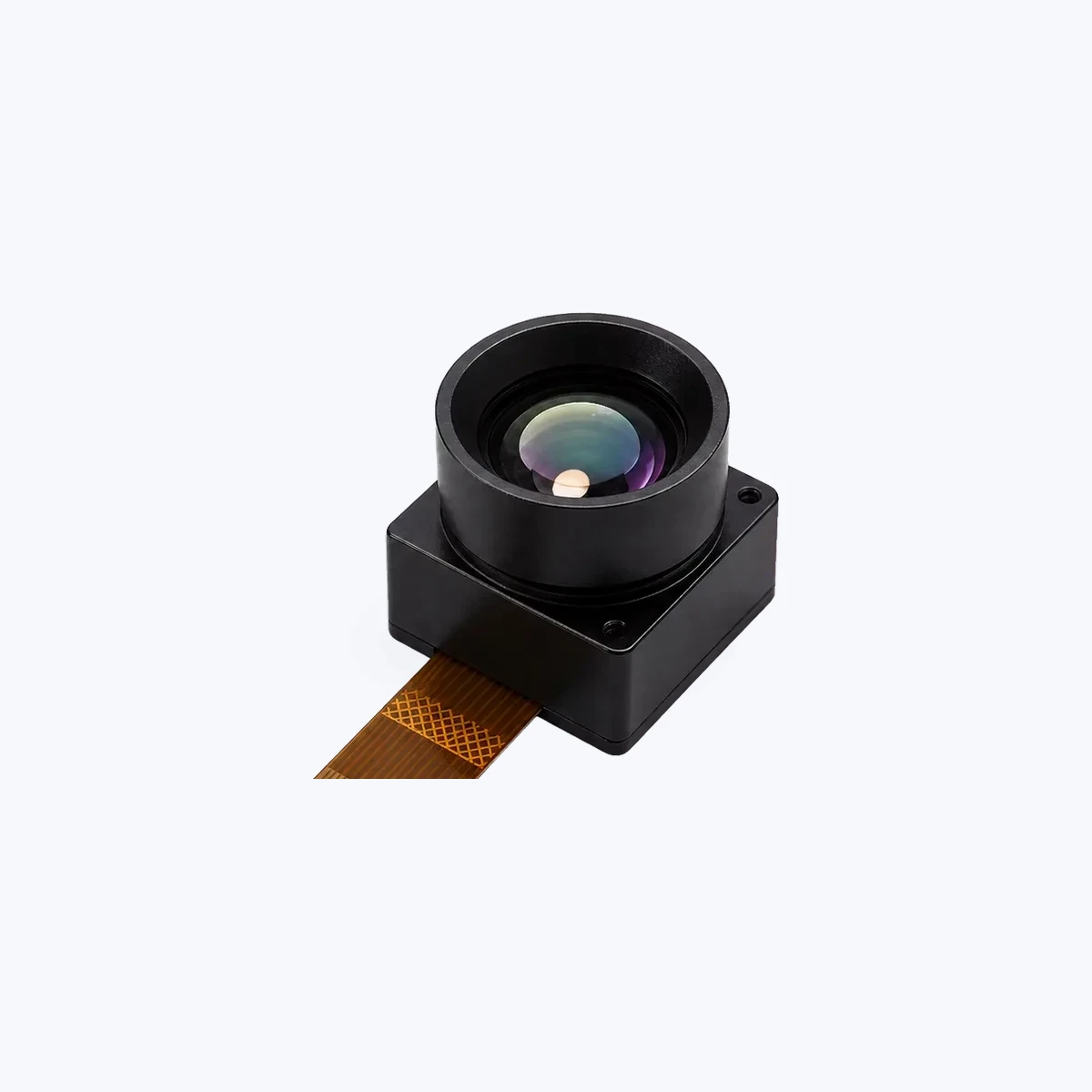
The CAMCUDA TC160-NF is an ultra-compact 160 × 120 LWIR thermal core built for embedded micro-sensors, smart HVAC monitoring, IoT devices, and distributed perimeter spot-detection nodes. Pulling only 76 to 78 mW over a single 3.3 V rail, it lets engineering teams drop calibrated thermal detection into space-constrained housings without busting their power budget.
Key Specifications (TC160-NF)
| Category | Specification Details |
|---|---|
| Product Model & SKU | TC160-NF / SKU: MI1602M5S |
| Detector Type | Uncooled LWIR Microbolometer Module |
| Array Resolution | 160 × 120 pixels (19,200 active pixels reference) |
| Detector Pitch | 35 µm reference |
| Spectral Band | 8 to 14 µm (LWIR) |
| Frame Rate | Up to 25 FPS |
| Field of View (FOV) | 56° / 45° / 34° in D / H / V order (Narrow-FOV fixed optical path) |
| Supply Voltage | 3.3 V DC |
| Power Consumption | Low-power operation: ~76 to 78 mW reference |
| Host Interface | SPI (Serial Peripheral Interface) |
| Physical Connector | 10-pin FPC, 0.5 mm pitch reference |
| Operational Temperature | -20 °C to +85 °C reference |
| Thermal Calibration | Factory-calibrated thermal output |
View Product Details & Pricing ➔
Direct Technical Comparison: CAMCUDA FlexMini 640 vs. TC160-NF
When you are choosing between a high-density security core and a low-power embedded module, look at how spatial resolution, power consumption, interfaces, and lens flexibility map to your operational needs:
| Architecture Factor | CAMCUDA FlexMini 640 | CAMCUDA TC160-NF |
|---|---|---|
| Target Application | Perimeter CCTV, border surveillance, PTZ turrets, aerial UAV gimbals | Embedded IoT sensors, smart HVAC monitoring, compact presence detection |
| Sensor Resolution | 640 × 512 (327,680 pixels) | 160 × 120 (19,200 pixels) |
| Pixel Pitch | 12 µm (High spatial density) | 35 µm (Reference) |
| Frame Rate | 50 Hz (Smooth high-speed tracking) | Up to 25 FPS |
| Power Budget | <0.7 W (5 to 24 V DC input) | ~76 to 78 mW (3.3 V DC input) |
| Optical Flexibility | Factory-installed: 4.1, 4.9, 9.1, 13, 19, 35 mm | Fixed narrow-FOV integrated optical assembly |
| Max Human Detection | Up to 3,402 m (35 mm lens configuration) | Short-range presence (<50 m reference) |
| System Integration Path | MIPI CSI-2, USB UVC, or CVBS analog video | SPI bus over 10-pin 0.5 mm FPC ribbon |
5. Optomechanical Integration, Protective Windows, and Thermal Dissipation
Boxing up a bare OEM thermal imaging core inside an IP66/IP67 environmental enclosure is not like packaging a visible security camera. Uncooled microbolometers bring unique optical and thermal dissipation challenges that will ruin your image if you do not design for them upfront.
Protective Housing Optical Windows
You cannot use standard glass, acrylic, or polycarbonate dome viewports on a thermal camera housing; they completely block the 8–14 µm LWIR spectrum. You must install a dedicated infrared-transmitting window directly in front of the core’s objective lens:
- ⚙️ Window Substrate Selection: High-purity optical Germanium (Ge) or durable Chalcogenide glass disks are mandatory. The window must have double-sided Broadband Anti-Reflective (BBAR) coatings to guarantee ≥92% optical throughput across the 8–14 µm band.
- ⚙️ Diamond-Like Carbon (DLC) Coating: The outward-facing side of the Germanium window must feature a DLC hard coating. This stops wind-blown sand from pitting the optic, protects against caustic fumes in chemical facilities, and prevents corrosion from marine salt spray.
- ⚙️ Optical Transmissivity Calibration: Every protective window cuts incoming thermal flux by 3% to 8%. If your camera is measuring temperatures (like switchgear monitoring or battery energy storage fire watch), you must program this optical transmission attenuation factor into the core’s radiometric calibration lookup table to preserve ±2 °C accuracy.
- ⚙️ Eliminating the Narcissus Effect: If you mount a flat Germanium window exactly parallel to the focal plane array, the cold microbolometer sensor can see its own reflected thermal signature. This shows up as a dark, circular cold spot right in the center of your image. To kill the Narcissus effect completely, mount the protective window tilted at an angle of 1.5° to 3.0° relative to the optical axis.
Thermal Isolation and Conductive Dissipation
Uncooled microbolometer arrays are sensitive to thermal gradients inside the housing. While the core has built-in digital temperature compensation curves, rapid, uneven heat spikes will cause fixed-pattern noise drift, corner vignetting, and trigger frequent, annoying NUC shutter clicks as the sensor tries to recalibrate itself.
Follow these baseline mechanical rules when designing your enclosure:
- ⚙️ Rule 1: Isolate Heat-Generating Electronics: Keep your high-power embedded Linux SoC, Power-over-Ethernet (PoE+ 802.3at) PD circuits, and step-down switching regulators on a physically separate PCB, spaced away from the thermal core mounting block.
- ⚙️ Rule 2: Direct Chassis Conduction: Couple the rear aluminum housing of the thermal core directly to the camera’s outer die-cast metal enclosure using a high-conductivity thermal gap pad (≥ 3.0 W/m·K). This turns the entire camera chassis into a giant passive heatsink, bleeding heat off into the outside air.
- ⚙️ Rule 3: Zero Axial Strain on the Lens: When clamping the core into the chassis, never apply radial or axial clamping force directly to the Germanium lens barrel. Mechanical strain shifts internal optical spacing by micrometers, causing focus shift and optical misalignment across seasonal temperature swings.
6. Deep-Dive Engineering FAQ
Can direct sunlight permanently damage a thermal CCTV camera sensor?
How do you connect an OEM thermal imaging core to standard IP CCTV and NVR systems?
What is the impact of weather (fog, rain, snow) on thermal CCTV camera range versus visible optical cameras?
Why is Non-Uniformity Correction (NUC) necessary, and what is the difference between shutter and shutterless NUC?
📚 References & Further Reading
- Industry Standard: OpenCV – Open Source Computer Vision and Image Processing Library
- Industry Standard: Wikipedia – Edge Computing Architectures & Real-Time Processing
- Related Guide: CAMCUDA 640×512 UAV Thermal Imaging Camera Integration
- Related Guide: CAMCUDA Multi-Sensor Drone Camera Payloads
- Technical Resources: CAMCUDA Technical Support, Pinouts, and SDK Portal