UAV FLIR Camera Selection Guide: OEM Cores, Dual-Spectrum Payloads & Protocols
Integrating forward-looking infrared imaging and long-wave infrared (LWIR) optical payloads into unmanned aerial vehicles (UAVs) is an engineering balancing act. If you’ve spent late nights on the bench fighting thermal drift or electrical noise, you know the drill: Size, Weight, Power, and Cost (SWaP-C) must be considered alongside video interfaces, power distribution, and control links.
FLIR is also the Teledyne FLIR brand; LWIR describes a spectral band. This guide uses the search term UAV FLIR camera to discuss selection questions, while identifying branded FLIR products and CAMCUDA modules separately. A generic LWIR module is not automatically a FLIR product or a compatible replacement. Single-sensor and dual-spectrum electro-optical/infrared (EO/IR) payloads both have a place, depending on the inspection task.
Picking the right UAV FLIR camera setup comes down to understanding the underlying physics and the delivered configuration. Detector chemistry, pixel pitch, optical field of view (FOV), onboard neural compute (TOPS), and host interfaces all affect the result.
For infrastructure inspection, environmental observation, and search support, start with the detail you need to see, whether you need temperature measurements, and how images will reach the operator or application. This guide walks through the mechanical, optical, electrical, and computational parameters to confirm before integrating an OEM thermal payload.
Table of Contents
- 👉 1. Understanding UAV FLIR Camera and LWIR Architectures: Physics, Sensor Materials, and SWaP-C
- 👉 2. Dual-Spectrum Sensor Integration: Optical Alignment, Dual-Light Fusion & PIP
- 👉 3. Hardware Interfaces & Flight Telemetry: MIPI, USB, CRSF, and ArduPilot Integration
- 👉 4. Radiometric Thermography vs. Thermal Imaging Payloads
- 👉 5. OEM Dual-Spectrum Module Specifications & Direct Comparison
- 👉 6. Step-by-Step Airframe Integration & Bench Testing Checklist
- 👉 7. Frequently Asked Questions (FAQ)
1. Understanding UAV FLIR Camera and LWIR Architectures: Physics, Sensor Materials, and SWaP-C
Long-wave infrared (LWIR) imaging commonly uses the 8 to 14 micrometer (μm) atmospheric window. Visible-light electro-optical (EO) sensors depend on solar rays or artificial illuminators reflected by a scene. Thermal cameras measure infrared radiation reaching the detector, including emission and reflected radiation from the scene.
This allows imaging without visible illumination, but darkness performance is not an all-weather guarantee. Fog, rain, humidity, smoke conditions, and weak thermal contrast can reduce usable detail. LWIR does not provide a general ability to see through foliage or other solid obstructions. FLIR explains these weather limitations.
Inside an airborne payload, the thermal core sits at the front line of an electro-optical signal chain. Incident infrared radiation passes through optics designed for the camera’s spectral band. In an uncooled microbolometer, suspended pixel membranes absorb radiation, warm slightly, and change electrical resistance; the readout electronics convert the response into image data.
Non-Uniformity Correction (NUC), bad-pixel replacement, and image enhancement can prepare that data for display or analysis. Raw bit depth, output formats, correction behavior, and processing order vary by core and firmware. Verify which data the selected interface exposes instead of assuming every camera provides raw 14-bit or 16-bit frames.
Detector Chemistry: Vanadium Oxide (VOx) vs. Amorphous Silicon (a-Si)
When you are sourcing an OEM thermal core, microbolometer material is one design variable. Compare the complete camera specification, including Noise Equivalent Temperature Difference (NETD), optics, frame rate, correction behavior, and operating conditions:
- ✅ Vanadium Oxide (VOx): VOx microbolometers are used in many uncooled cameras. The Teledyne FLIR Boson Plus OEM is a documented example. Its published sensitivity applies to that product and specified conditions, not to every VOx detector. Request comparable NETD test conditions, lens f-number, and frame settings when evaluating cores.
- ⚙️ Amorphous Silicon (a-Si): Amorphous silicon is another established microbolometer material. Material name alone does not rank finished cameras for noise, thermal response, price, or image quality. Compare measured performance under matched conditions; assess motion blur and temporal filtering with your own inspection scenes.
Pixel Pitch, Resolution Scaling, and Optical Mechanics
The geometric layout of your focal plane array directly impacts optical packaging and spatial sampling. At the same focal length, smaller pixel pitch gives finer angular sampling; at a similar pixel-pitch-to-focal-length ratio, a shorter lens can preserve approximately the same sampling. A smaller detector format can support a more compact optical design.
These relationships do not guarantee a lighter finished payload. Lens aperture, f-number, image quality, housing, and mounting still matter. Compare the complete lens-and-core assembly when estimating gimbal loads and aircraft balance. Use our Thermal Imaging Calculator for preliminary field-of-view and angular-sampling estimates, then validate the actual lens and required inspection detail in representative scenes.
A 640 x 512 array is one useful option for airborne thermal imaging, but resolution should follow the required inspection detail and field of view. A native 1280 x 1024 detector has four times as many pixels as 640 x 512; it does not automatically deliver four times the usable range. Optics, contrast, atmosphere, and the definition of a successful observation still matter.
If native 1280-class acquisition is a requirement, request evidence for the actual detector and output mode. A 640-class image enlarged by software does not meet that requirement. The current CAMCUDA product catalog can support configuration inquiries; confirm a documented native 1280 option rather than relying on an obsolete model listing.
2. Dual-Spectrum Sensor Integration: Optical Alignment, Dual-Light Fusion & PIP
An uncooled LWIR sensor is useful for distinguishing thermal contrast, but thermal alone leaves gaps in scene interpretation. Visible color, fine surface texture, and readable markings can add context that a thermal image does not provide reliably. Their visibility depends on optics, resolution, illumination, and distance.
Dual-spectrum payload design pairs a visible-light (EO) sensor with a thermal (LWIR) core. This can help an operator relate a warm component to the surrounding structure during inspection, provided the views are aligned and their differences are understood.
Optical Parallax and Real-Time Homography Calibration
When you place two optical sensors side-by-side, you introduce baseline parallax. Their different viewpoints can make a nearby object appear at different positions in the visible and thermal images, while distant scene features are closer to alignment. Different lens fields of view, distortion, and mounting tolerances add further registration differences.
A homography can align images for a plane or an approximate reference distance. It does not remove depth-dependent parallax across a scene containing objects at different distances. Calibrate lens distortion and sensor alignment, then check residual errors at the distances relevant to the inspection. Depth-aware methods may be needed where a single transform is insufficient; do not assume an AI processor supplies automatic, accurate fusion. OpenCV documents the geometric limits of homography.
Dual-Light Fusion versus Picture-in-Picture (PIP) Implementations
Depending on whether the primary consumer is a human operator or a computer-vision application, consider how multi-spectral data is displayed and processed:
- ⚙️ Edge-Extraction Fusion: A fusion implementation may extract structural outlines from the visible feed and overlay them on the thermal image. This can combine thermal contrast with visible context, but depends on spatial registration, timing, and the selected algorithm. It does not increase the thermal detector’s native resolution. For broader airframe considerations, review our drone thermal camera application guide.
- ✅ Picture-in-Picture (PIP) Overlay: PIP places one camera view inside another, helping an operator compare thermal detail and visible context without requiring pixel-level fusion. Confirm selectable views, output resolution, and timing for the delivered firmware. VisionCube lists PIP support; that alone does not establish registered image fusion.
3. Hardware Interfaces & Flight Telemetry: MIPI, USB, CRSF, and ArduPilot Integration
A UAV FLIR camera payload is only as useful as its data pipelines and control links. Define the required video format, frame rate, recording path, and operator controls before selecting an interface. End-to-end delay includes exposure, processing, buffering, transport, and display; a bus name alone cannot establish that delay.
Video Data Protocols: MIPI-CSI2 vs. USB UVC
Two common interface approaches are MIPI-CSI2 and USB. They have different integration requirements, and neither is automatically available on a particular module:
- ⚙️ MIPI-CSI2 (Camera Serial Interface 2): MIPI-CSI2 is an embedded camera interface that can feed a compatible host’s imaging pipeline. Integration depends on supported lane configuration, data format, electrical connection, and host software. It can suit a tightly integrated design, but has no universal sensor-to-memory latency and does not guarantee direct NPU access. MIPI describes the CSI-2 interface.
- ✅ USB (USB Video Class / Direct Digital Capture): Standards in the USB-IF Document Library include USB Video Class (UVC). A camera that implements UVC may use a host class driver for supported modes, while other USB cameras require vendor software. Verify the class, payload format, bandwidth, operating system, and control features. VisionCube lists a USB thermal interface; UVC support has not been established for the selected variants.
Flight Telemetry and Payload Control: CRSF, MAVLink, and Flight Controller Stacks
Payload control and video transport are separate integration questions. A serial UART describes an electrical interface, not the commands or message definitions carried over it. Some systems need a companion computer or a documented adapter between the camera and flight controller. Confirm supported functions on both ends before making a connection.
- ⚙️ CRSF (Crossfire Protocol): CRSF is used for receiver and flight-controller communication. It does not, by itself, establish camera palette, PIP, or application control. Those functions need a documented implementation in the payload and host. Verify the specific firmware and control mapping instead of inferring compatibility from a serial connector.
- ✅ MAVLink and Flight Controller Support: MAVLink defines messages and camera services, but each camera, bridge, and flight stack implements a particular subset. ArduPilot, PX4, and BetaFlight support must be checked against the exact hardware and firmware. For civilian inspection, define the operator’s required viewing and recording controls, then validate them on the bench; no native integration is established here for VisionCube. See the MAVLink camera capability documentation.
4. Radiometric Thermography vs. Thermal Imaging Payloads
System integrators need to distinguish thermal image contrast from calibrated temperature measurement. A radiometric payload provides data and calibration for temperature estimation under specified conditions. A thermal imaging module may show useful contrast without providing a supported temperature reading. Radiometry and onboard AI are separate capabilities; one does not inherently exclude the other.
| Engineering Metric | Calibrated Radiometric Payload | Thermal Imaging / AI Module |
|---|---|---|
| Primary Mission Goal | Estimate scene temperatures (°C/°F) within stated measurement conditions. | Show thermal contrast and, where supported, support image analysis. |
| Calibration Data & LUTs | Calibrated temperature conversion with specified range, accuracy, and environmental inputs. | NUC and image enhancement do not by themselves establish temperature accuracy. |
| Pipeline Latency | Measure the selected output and processing path; radiometry alone does not determine latency. | Measure the same complete path and settings; image-only output is not inherently faster. |
| Embedded AI Hardware | May use onboard or host processing; verify the selected product. | May include an NPU; verify model support and application throughput. |
| Primary Flight Use-Case | Quantitative inspection of solar panels, electrical assets, or civil infrastructure. | Visual observation, qualitative inspection, and scene interpretation. |
| Complete Project Cost | Include calibration requirements, optics, mounting, software, and integration support. | Include host hardware, wiring, software work, testing, and maintenance. |
Image enhancement such as automatic gain control (AGC), Digital Detail Enhancement (DDE), or histogram-based contrast adjustment can make a thermal view easier to interpret. These operations do not create calibrated temperature data. When quantitative inspection is required, confirm measurement range and accuracy, emissivity handling, reflected temperature, and the effects of distance and atmosphere. See FLIR’s measurement-parameter guidance.
5. OEM Dual-Spectrum Module Specifications & Direct Comparison
For engineering teams comparing dual-spectrum payloads for civilian inspection and observation, the current CAMCUDA AI VisionCube ST Pro and DT Pro configurations provide a useful example. Both list 640 x 512 thermal imaging, while their visible-camera arrangements and AI compute differ.
The values below follow the current VisionCube specification tables. Rows marked as tests or documentation requests are selection criteria, not verified performance specifications. Confirm the delivered revision, camera bill of materials, and software before committing an airframe design.
| Specification Parameter | CAMCUDA AI VisionCube ST Pro | CAMCUDA AI VisionCube DT Pro |
|---|---|---|
| AI Processing Engine | 1 TOPS | 6 TOPS |
| Thermal Detector Type | LWIR thermal imaging; request detector-material confirmation | LWIR thermal imaging; request detector-material confirmation |
| Thermal Resolution & Rate | 640 x 512 @ 50 Hz | 640 x 512 @ 50 Hz |
| Thermal Band & Pixel Pitch | 8–14 μm / 12 μm Pixel Pitch | 8–14 μm / 12 μm Pixel Pitch |
| Thermal Optics & FOV | 9.1 mm; 45.9° H × 36.9° V | 9.1 mm; 45.9° H × 36.9° V |
| EO Camera & Output | Single visible; 1920 × 1080 at 30 Hz; listed CMOS 1/2.8 inch | Dual visible; 1920 × 1080 at 30 Hz; confirm final CMOS bill of materials |
| EO Optics & FOV | 4 mm; 69° H × 42° V | 3.9 mm wide: 72° H × 45° V; 12 mm telephoto: 26° H × 15° V |
| Visible Low-Light Qualification | No minimum-lux rating verified; test image usability with stated exposure and gain | No minimum-lux rating verified; test both visible channels with stated exposure and gain |
| Inspection Detail / Distance Test | Measure whether the required feature is resolved at the planned inspection distance | Measure wide and telephoto detail at the same inspection distances |
| Concurrent Inference Workload | Request supported model and task limits; benchmark the intended inspection workload | Request supported model and task limits; benchmark the same inspection workload |
| Viewing & Processing Modes | Picture-in-picture listed; confirm fusion and application features for the delivered firmware | Picture-in-picture listed; confirm channel switching, fusion and application features for the delivered firmware |
| End-to-End Latency Test | Measure acquisition-to-display or acquisition-to-application delay using the chosen output path | Measure the same complete path and settings |
| Image Quality in Motion | Test blur, frame continuity and usable detail under the inspection movement profile | Test each visible channel and thermal stream under the same movement profile |
| Control & Host Integration | Thermal USB listed; request revision-matched pinout, protocol, driver and SDK information | Thermal USB listed; dedicated AI interface. Request matching pinout, protocol, driver, and SDK information. |
| Board Input, Mounting & Mass | Board reference: 9–16 V; 38 × 38 × 29 mm; mounting 25.5 × 25.5 mm; 43.8 g | Board reference: 9–16 V; 38 × 38 × 29 mm; mounting 25.5 × 25.5 mm; 43.8 g |
| Camera Dimensions & Mass | Visible camera: 19 × 19 × 30 mm. Thermal: 26 × 26 × 21.1 mm and ≤23 g, excluding lens and connectors | Dual-visible camera: 40.8 × 25 × 26 mm. Thermal: 26 × 26 × 21.1 mm and ≤23 g, excluding lens and connectors |
Comprehensive Overview: CAMCUDA AI VisionCube ST Pro
The CAMCUDA AI VisionCube ST Pro pairs a single visible camera with 640 x 512 thermal imaging and 1 TOPS AI processing. It is an option to evaluate for compact inspection and observation payloads when one visible view meets the task.
The common processing-board reference is 38 x 38 x 29 mm, with a 25.5 x 25.5 mm mounting pattern and 43.8 g board mass. These are component figures, not the dimensions or weight of the complete camera assembly. Check the full mounting envelope, cables, lens clearance, and aircraft balance.
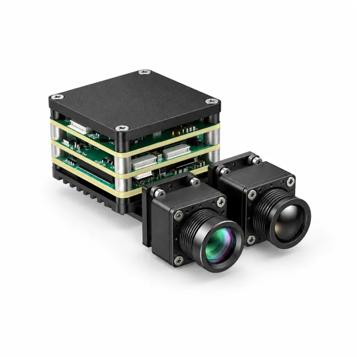
Official AI VisionCube ST Pro gallery illustration. Request a revision-matched drawing for connector and mounting details.
The visible channel lists a 4 mm lens with a 69° horizontal by 42° vertical FOV and 1920 x 1080 output at 30 Hz. The thermal channel lists 640 x 512 at 50 Hz, 12 μm pixels, an 8–14 μm spectral response, and a 9.1 mm lens with a 45.9° horizontal by 36.9° vertical FOV.
The visible sensitivity entry is not a minimum-illumination lux rating. Thermal imaging does not require visible light, but usable detail still depends on scene contrast, optics, and the environment.
The 1 TOPS rating describes compute capability, not a guaranteed number of detections, application frame rate, or end-to-end delay. PIP is listed for the family; confirm other viewing and processing features for the delivered firmware. The thermal interface is listed as USB, and the processing-board input reference is 9–16 V.
Before wiring a UAV FLIR camera or another LWIR payload, obtain the exact connector drawing, power requirements, supported host software, and control protocol. The product page supplies the listed specifications. Request a model- and revision-matched PDF, SDK documentation, pin map, and assembly drawings for ST Pro before planning connections or mounting.
Select ST Pro & View Current Details ➔
Comprehensive Overview: CAMCUDA AI VisionCube DT Pro
The CAMCUDA AI VisionCube DT Pro combines dual visible cameras, 640 x 512 thermal imaging, and 6 TOPS AI processing. The visible wide-angle and telephoto views give an operator different framing options for inspection and observation. Choose between ST Pro and DT Pro by matching the visible views and processing requirements to the task.
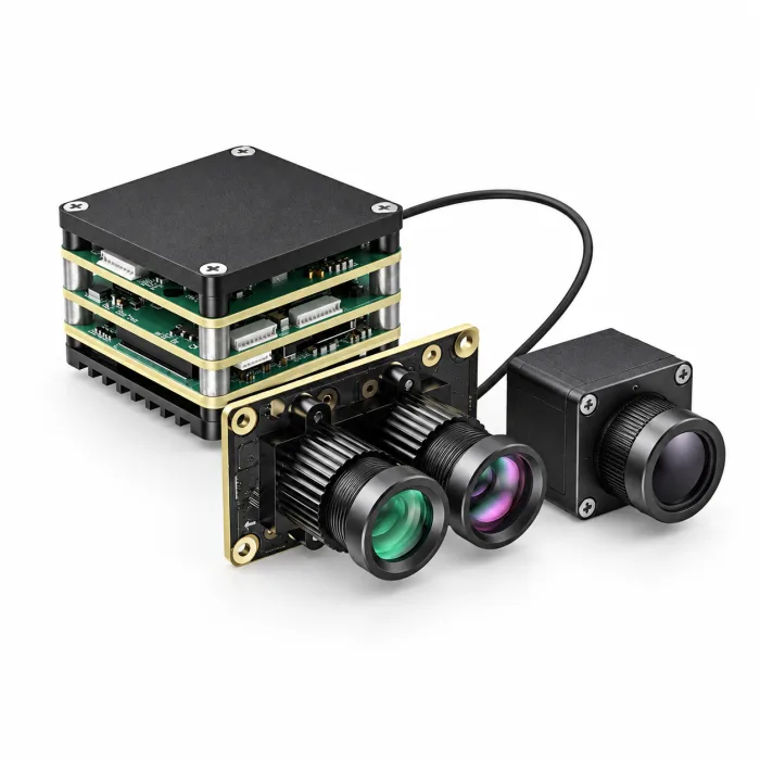
Official AI VisionCube DT Pro gallery illustration. This model view is not a pin map or a dimensioned mechanical drawing.
The DT Pro visible optics are a 3.9 mm wide-angle lens with a 72° horizontal by 45° vertical FOV and a 12 mm telephoto lens with a 26° horizontal by 15° vertical FOV. Listed visible output is 1920 x 1080 at 30 Hz. The thermal entries match ST Pro: 640 x 512 at 50 Hz, 12 μm pixels, 8–14 μm response, and 9.1 mm optics with a 45.9° by 36.9° FOV.
A narrower visible view can show a smaller area in greater image detail, but makes framing and motion sensitivity more important. Compare both channels on the intended inspection scene; the 6 TOPS figure does not establish speed, detection range, or tracking accuracy.
DT Pro has a dedicated AI interface; obtain its revision-matched electrical and software documentation before planning host integration. Do not infer a shared SDK, pin-compatible connector, or CRSF/MAVLink support from the family name. The listed dual-visible camera dimensions are 40.8 x 25 x 26 mm. The Pro thermal camera is listed at 26 x 26 x 21.1 mm and ≤23 g, excluding lens and connectors.
The common board dimensions and mass in the table are not a complete-kit specification. Request the assembled envelope and mass along with included accessories, software, and thermal-management requirements. For wider application context, see our inspection and observation application library.
Select DT Pro & View Current Details ➔
6. Step-by-Step Airframe Integration & Bench Testing Checklist
Wiring an LWIR core and processing board to an airframe requires systematic electrical, thermal, and RF validation. Use this five-stage integration checklist to plan bench work. Apply the selected module’s approved requirements and keep aircraft propulsion disabled during initial payload checks.
Stage 1: Power Supply Conditioning & Grounding
- ⚙️ Plan DC-DC Regulation: Check the full aircraft supply range, startup current, load transients, polarity, and the payload’s input limits. Select a regulated power path where required by the module and aircraft design. VisionCube’s 9–16 V figure is a processing-board input reference, not permission to apply that voltage to every connector.
- ⚙️ Verify Ripple on the Scope: Measure supply behavior at the payload under representative loads using an appropriate probe setup. Compare ripple and transient peaks with the supplier’s limits. Filter and capacitor choices must account for regulator stability, current, voltage rating, and the actual noise spectrum; there is no universal ripple or capacitor value for every payload.
- ✅ Review Grounding: Follow the board and interface documentation for power returns, signal references, and shielding. Check voltage differences and return-current paths before connecting video or serial signals. A star-ground layout is one possible design choice, not a guaranteed fix for every digital or mixed-signal system.
Stage 2: Thermal Management & Convection Pathing
- ⚙️ Verify the Cooling Path: Assess processor and camera temperatures in the intended enclosure and workload. Check the supplier’s mounting and cooling instructions, including stationary operation when aircraft airflow is absent. TOPS alone does not specify heat output or the cooling hardware required.
- ✅ Limit Unwanted Thermal Coupling: Nearby processors, transmitters, and power electronics can change the camera’s thermal environment. Check warm-up, drift, and NUC behavior under representative conditions. Select separation or thermal isolation from measurements and the camera documentation, rather than an arbitrary transmitter power threshold.
Stage 3: EMI/RFI Shielding & High-Speed Data Lines
- ⚙️ Route Data Cables as Specified: Follow the interface’s cable, impedance, grounding, and shielding requirements. Poor routing or shielding can affect signal integrity and electromagnetic compatibility. Do not apply conductive tape without an approved bonding and insulation plan.
- ✅ Check RF Coexistence: Test video continuity, control links, and navigation reception with the intended onboard electronics operating. Adjust routing and separation based on the system design and measured interference. A fixed clearance does not establish compatibility for all boards, cables, or antennas.
Stage 4: Flight Controller Telemetry & Protocol Configuration
- ⚙️ Confirm Interfaces Before Wiring: Obtain the exact connector pinout, signal voltage, direction, and supported protocol for both devices. Set baud rate and message configuration from the matched documentation. Do not solder a presumed UART or apply a generic CRSF/MAVLink setting to an unverified camera interface.
- ⚙️ Map Supported Operator Controls: Document the viewing and recording functions actually exposed by the payload and host software, such as:
- 👉 Available palettes and visible/thermal display selection.
- 👉 Supported PIP or camera-view switching.
- 👉 Recording controls and status feedback.
- ✅ Validate Loss and Recovery Behavior: On the bench, check camera power loss, video interruption, and control-link loss against the aircraft’s approved safety requirements. Record the expected indication, recovery sequence, and operator response. Do not assume retaining the last state is the right behavior for every system.
Stage 5: Bench Optical Alignment & Sensor Fusion Tuning
- ⚙️ Check Optical Registration: Use suitable visible and thermal reference features at the working distances and depths of the inspection. Check lens distortion, timing, and alignment across the image. A single homography or offset may leave depth-dependent parallax; record the residual error rather than promising complete correction.
- ✅ Tune Available DDE and AGC Controls: Where the delivered firmware exposes these settings, assess contrast and detail on representative surfaces and temperatures. Keep a record of settings, raw data availability, and repeatability. If the task requires temperature measurements, validate the radiometric output separately from the display palette.
7. Frequently Asked Questions (FAQ)
Can I integrate an OEM UAV FLIR or LWIR camera module directly with flight controllers like ArduPilot or BetaFlight?
Direct integration depends on the exact module, host, electrical interface, and implemented protocol. UART, USB, CRSF, and MAVLink labels do not guarantee matching commands or supported video formats. Request the revision-matched pinout, driver or SDK requirements, and a list of supported functions for ArduPilot, PX4, or BetaFlight. A companion computer or adapter may be needed. VisionCube lists a USB thermal interface; native flight-controller integration and UVC support are not established by that entry.
How should OEM builders compare the cost of turnkey FLIR drone payloads and modular LWIR alternatives?
A turnkey payload price can include optics, a stabilized gimbal, calibrated measurement features, software, mechanical integration, and support. An OEM core may offer more freedom over mounting, lens selection, host hardware, and wiring, but transfers integration and validation work to the builder. Compare complete project cost, including development time, accessories, maintenance, and acceptance testing. There is no supported universal savings percentage. Match the actual capabilities required; CAMCUDA modules are not presented here as FLIR-branded or automatically compatible replacements.
What is the practical difference between a UAV thermal imaging module and a calibrated radiometric camera?
A thermal imaging module provides scene contrast for observation or qualitative inspection. A calibrated radiometric camera also supplies supported temperature estimates within stated ranges and accuracy conditions. Those estimates depend on factors such as emissivity, reflected radiation, atmosphere, and viewing geometry. Radiometry does not inherently rule out high frame rates or AI processing, and image-only output does not guarantee lower latency. Select and test the required measurement, display, and analysis functions together. The current VisionCube listing does not establish calibrated temperature range or accuracy.
📚 References & Further Reading
- Documented FLIR Product Example: Teledyne FLIR Boson Plus OEM Thermal Cores
- Interface Standards: USB-IF Document Library & UVC Specifications
- Related Engineering Guide: Industrial Drone Thermal Camera System Design
- Payload Applications: Inspection and Observation Applications
- Current Configuration Specifications: VisionCube ST Pro and DT Pro visible, thermal, and board specifications
Technical author: Daniel · Hardware Support
Sales contributors: Vivian, Lena and Sophie.