Thermal Camera on Drone: OEM Core Selection, SWaP & Integration Guide
Thermal Camera on Drone: OEM Core Selection, SWaP & Integration Guide
Deploying a high-performance thermal camera on drone platforms comes down to a tough balancing act: sensor physics on one side, brutal aeronautical constraints on the other. Look, uncooled Long-Wave Infrared (LWIR) payloads require thermal sensitivity appropriate to the application, fast frame integration, and wide optical throughput—all while living inside unforgiving size, weight, power, and cost (SWaP-C) budgets. Whether you are engineering sub-250g micro-UAVs for close-up industrial pipe inspection or building heavy-lift multi-rotors for civilian search and rescue (SAR), you can’t treat an OEM thermal imaging core like a standard plug-and-play USB webcam.
Microbolometer response times, lens aperture sizing (F-number), non-uniformity correction (NUC) shutter cycles, and electromagnetic noise bleeding off motor Electronic Speed Controllers (ESCs) will make or break your flight payload.
In the shop, system integrators navigate a wide spectrum of OEM hardware: everything from compact uncooled Vanadium Oxide (VOx) bare cores to dual-spectrum electro-optical/infrared (EO/IR) modules such as the 1 TOPS AI VisionCube ST Pro. Nailing the right architecture means digging into the trade-offs: raw analog CVBS versus digital MIPI/USB video latency, optical Detection, Recognition, and Identification (DRI) ranges via Johnson’s criteria, and managing trapped thermal heat inside sealed 2-axis or 3-axis brushless gimbals. This engineering guide cuts through the marketing fluff to break down the core sensor physics, optical calculations, interface pipelines, and flight-stack hooks you need to integrate OEM thermal hardware into modern unmanned systems successfully.
Table of Contents
- 👉 1. Thermal Core Sensor Physics & UAV Integration Fundamentals
- 👉 2. SWaP-C Optimization in Aerial Gimbal & Airframe Design
- 👉 3. Optical Engineering: Focal Length, IFOV, and Johnson’s Criteria Calculations
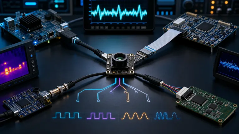
- 👉 4. Interface Pipelines: CVBS, USB UVC, and MIPI CSI-2 Video Transmission
- 👉 5. Dual-Spectrum EO/IR Fusion and Onboard Edge-AI Tracking
- 👉 6. Thermal Camera on Drone Platforms: OEM Hardware Specifications
- 👉 7. OEM Hardware Specification Matrix: Standalone Core vs. AI Payload
- 👉 8. Step-by-Step Airframe Integration & Bench Validation Protocol
- 👉 9. Frequently Asked Questions (Technical Deep-Dive)
1. Thermal Core Sensor Physics & UAV Integration Fundamentals
Airborne thermal imaging works by capturing emitted radiation across the Long-Wave Infrared (LWIR) spectrum between 8 and 14 micrometers. Standard visible-light electro-optical (EO) CMOS cameras record visible light emitted by or reflected from the scene. An aerial thermal core operates differently: it records infrared radiance influenced by surface temperature, emissivity, reflections, and the atmosphere. Because it doesn’t need visible illumination, thermal imaging can reveal useful contrast in darkness and some smoke conditions. Haze, rain, fog, and obstructions can still reduce visibility; the image alone does not establish safe flight clearance.
When you’re building for UAVs, evaluate detector response alongside complete-camera performance and the intended operating environment. Vanadium Oxide (VOx) and Amorphous Silicon (a-Si) are both established microbolometer materials. Material choice alone does not determine finished-camera sensitivity. The AeroMini 640 specifies Noise Equivalent Temperature Difference (NETD) of ≤30 mK (0.03°C) at 25°C and F1.0. Up in the air, your thermal core takes a beating from continuous propeller downwash, turbulent ambient airflow, and rapid altitude changes.
A low NETD can help reveal subtle surface-temperature patterns during inspection, but contrast, optics, weather, and occlusion still govern what is visible. It does not establish temperature-measurement accuracy. For further reading, explore optics and photonics resources from Optica and the separate manufacturer overview from InfraTec Infrared Cameras.
The industry shift from legacy 17 μm microbolometer pixel arrays to modern 12 μm pixel pitch architectures has changed drone gimbal design. Here’s why: a 12 μm 640 x 512 Focal Plane Array (FPA) shrinks the physical active sensor area by roughly 50% compared to an older 17 μm array with the same resolution. That smaller die size cascades directly into your optics. A shorter focal length lens can now match the exact Field of View (FOV) of an older, bulkier 17 μm setup.
Because LWIR lenses commonly use materials such as Germanium or Chalcogenide glass, using smaller optical elements cuts payload mass and bill-of-materials costs dramatically. But there is an engineering catch: packing pixels down to 12 μm tightens optical tolerances and increases vulnerability to thermal defocus as the lens housing expands or contracts. Validate focus stability for the selected lens and enclosure across the intended operating temperatures; a module operating-temperature rating alone does not guarantee optical focus.
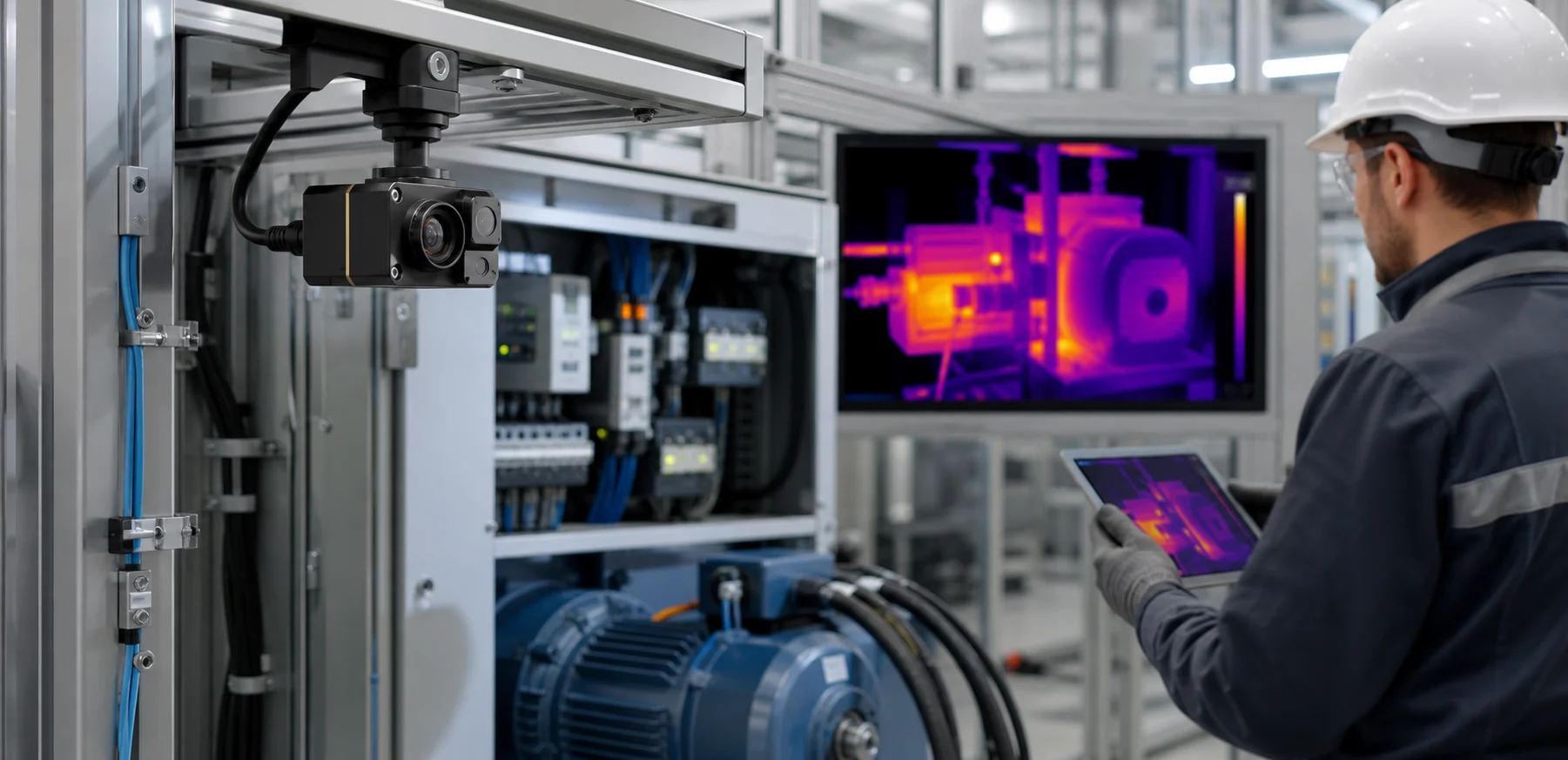
Frame rate is another non-negotiable operational spec. Choose the frame rate for the scene motion and full video pipeline. AeroMini non-radiometric imaging offers a 60 Hz factory default or 30 Hz factory option; VisionCube ST Pro lists 50 Hz thermal and 30 Hz visible output. Verify the delivered frame rate, motion blur, dropped frames, and latency on the exact output path rather than inferring them from a sensor-rate label.
2. SWaP-C Optimization in Aerial Gimbal & Airframe Design
Size, Weight, Power, and Cost (SWaP-C) dictate your flight envelope. Payload mass and mounting position affect flight endurance, aircraft center of gravity (CoG), and motor loading. For micro-UAVs targeting a sub-250g takeoff mass and larger civilian multirotors alike, your thermal camera must squeeze maximum analytical performance out of minimal physical mass.
Modern micro-sized thermal modules have radically lowered payload mass. AeroMini 640 specifies less than 20 grams without lens and flange; add the selected optics, board, wiring, mount, and gimbal to establish the complete payload mass. Keeping physical mass off the stabilized gimbal pitch and roll axes reduces rotational inertia (for a point-mass approximation, J = m × r2). That lower inertia can offer mechanical advantages on the aircraft:
- ✅ Tighter PID Tuning: Lower inertia can help Proportional-Integral-Derivative tuning, but loop stability and motor oscillation still require testing.
- ✅ Downsized Stators: Brushless gimbal motors can use smaller stators and draw less holding current, saving battery power across the entire airframe.
- ✅ Vibration Rejection: A correctly designed and tuned camera mount can reduce disturbances; verify residual vibration and image blur on the complete assembly.
Power handling and electrical noise resilience require just as much attention on the bench. Drones are electrically hostile environments. When pilots punch the throttle, brushless motor ESCs switch tens of amperes, generating severe voltage dips, inductive spikes, and electromagnetic noise across the power distribution board. Include any required regulator and filtering in the mass and thermal budget. AeroMini’s illustrated POWER_IN1 and POWER_IN2 pins require 5 V, while the VisionCube processing-board reference specifies 9–16 V. Match the supply to the exact board and verify transients and current capacity before connecting it.
AeroMini’s typical module consumption is <0.5 W at 25°C, but the complete kit and enclosure still require a thermal budget. Uncooled microbolometers rely on continuous internal temperature tracking to calculate calibration offsets. If an internal processor or poorly matched voltage regulator dumps waste heat into the camera casing, internal thermal gradients develop across the detector. Those gradients can increase non-uniformity and the need for correction. Measure NUC/FFC behavior and any image interruption on the selected firmware; AeroMini supports adjustment of available triggering settings through its PC software. For a step-by-step breakdown on handling airborne power isolation and grounding, check our bench guide on IR camera module drone OEM integration checks.
3. Optical Engineering: Focal Length, IFOV, and Johnson’s Criteria Calculations
Selecting optics for a drone thermal core is an early integration decision. Choose the AeroMini lens when ordering and confirm the approved service procedure before changing it: lens replacement can affect focus, alignment, sealing, and calibration where applicable. The featured non-radiometric configuration does not measure temperature. Your team needs to calculate target profiles, planned flight ceilings (Above Ground Level, or AGL), and operational tasks during the initial design phase.
The relationship between sensor resolution, pixel pitch, and lens focal length determines your Instantaneous Field of View (IFOV). IFOV represents the angular footprint covered by an individual detector pixel in milliradians (mrad), calculated as:
IFOV (mrad) ≈ [Pixel Pitch (μm) / Focal Length (mm)]
From the IFOV, estimate Ground Sampling Distance (GSD), the linear pixel footprint for a nadir view of locally flat terrain. Use height above that terrain; oblique views require projection geometry:
GSD (m) ≈ Height above terrain (m) × IFOV (mrad) × 10-3
Johnson’s Criteria provide approximate human-observer thresholds, conventionally associated with 50% task probability, rather than guaranteed operating ranges. A line pair is one light-dark cycle; the ideal sampling model below uses two pixel samples per cycle across a target’s critical dimension:
- ⚙️ Detection (1 cycle / 2 ideal pixel samples): The observer detects that an object is present.
- ⚙️ Recognition (4 cycles / 8 ideal pixel samples): The system distinguishes the general object class (e.g., differentiating a human being from a deer or vehicle).
- ⚙️ Identification (6.4 cycles / 12.8 ideal pixel samples): The observer distinguishes a more specific object type; the required detail and success rate must be defined for the application.
The table is a geometric example for a 640 x 512, 12 μm sensor using a 0.5 m target critical width. Range (m) = 0.5 / [sample count × IFOV (mrad) × 10-3], calculated before rounding. FOV assumes ideal rectilinear optics. These focal lengths are comparison examples, not the current AeroMini lens list or manufacturer DRI ratings; its selected 9 mm lens is distinct from the 9.1 mm example. Atmospheric loss, contrast, optics, motion, and processing can reduce usable range. Use the thermal imaging calculator to explore geometry, noting that its DRI thresholds are 1.5/6/12 pixels rather than the 2/8/12.8 samples used here; verify performance with representative images.
| Focal Length | Ideal FOV (H × V) | IFOV | Human Detection | Human Recognition | Human Identification | Example Evaluation Use |
|---|---|---|---|---|---|---|
| 4.1 mm | 86.2° × 73.7° | 2.93 mrad | DRI not evaluated for this example | Close-range inspection & situational awareness | ||
| 4.9 mm | 76.2° × 64.2° | 2.45 mrad | 102.08 m | 25.52 m | 15.95 m | Indoor SAR, close-quarters structural inspections, FPV |
| 9.1 mm | 45.8° × 37.3° | 1.32 mrad | 189.58 m | 47.40 m | 29.62 m | Civilian observation, SAR, utility mapping |
| 13 mm | 32.9° × 26.6° | 0.92 mrad | 270.83 m | 67.71 m | 42.32 m | Solar farm audits, high-voltage utility line inspection |
| 19 mm | 22.9° × 18.4° | 0.63 mrad | 395.83 m | 98.96 m | 61.85 m | Perimeter security, wildlife monitoring, high AGL watch |
| 35 mm | 12.5° × 10.0° | 0.34 mrad | 729.17 m | 182.29 m | 113.93 m | Distant infrastructure and landscape observation |
Wide-angle optics (like 4.9 mm) give your pilot comprehensive situational awareness across wide swaths of terrain, making them the sweet spot for close-quarters search and rescue. Narrow telephoto glass (such as 19 mm or 35 mm) gives a smaller pixel footprint at the same distance, but defect size, contrast, motion, and the required working distance still need validation. To explore cross-industry field deployments in detail, review our thermal camera applications overview.
4. Interface Pipelines: CVBS, USB UVC, and MIPI CSI-2 Video Transmission
Routing thermal video from your sensor core out to flight controllers, companion Single-Board Computers (SBCs), or RF broadcast transmitters demands an electrical interface matched to your latency budget and compute architecture.
Composite Video Baseband Signal (CVBS Analog)
CVBS is one option for a low-latency analog viewing path. AeroMini lists PAL/NTSC composite output, subject to the selected interface board; use its matched connector diagram rather than a generic Rx/Tx/video/power pinout. Avoiding external compression and network buffering can reduce delay, but sensor processing, any transmitter, receiver, and display still contribute. Measure the complete camera-to-display path: the available specifications do not establish a less-than-20-millisecond glass-to-glass guarantee.
USB UVC (USB Video Class)
USB UVC can simplify host capture when the delivered board and firmware implement a compatible UVC mode; confirm format, frame rate, driver, and connector requirements first. AeroMini provides Linux drivers, examples, and an SDK in USB-SDK.zip, while its standard configuration does not provide RAW or minimally processed video. Validate the exact host and capture pipeline before using frames in OpenCV or GStreamer. USB latency depends on buffering and processing, so measure it for the inspection or edge-AI workload instead of assuming a 30–60 ms range.
MIPI CSI-2 (Mobile Industry Processor Interface)
When you are building custom carrier boards and proprietary compute hardware, MIPI CSI-2 can connect a compatible camera output to the application processor’s video input. AeroMini’s MIPI configuration requires confirmation of the exact board, lane mapping, electrical interface, output format, firmware, and host driver. The interface name does not establish RAW bit depth, radiometry, simultaneous output rates, or sub-10 ms latency; the standard AeroMini configuration does not provide RAW or minimally processed video.
5. Dual-Spectrum EO/IR Fusion and Onboard Edge-AI Tracking
Standalone thermal sensors are great at picking out hot spots against cold backgrounds, but LWIR imagery has an inherent weakness: it lacks surface texture, typography, and optical color cues. Dual-spectrum systems solve this by mounting a high-resolution visible (EO) sensor right alongside a 640 x 512 uncooled thermal core on a single payload assembly.
The latest dual-spectrum payloads integrate dedicated neural processing hardware directly into the camera processing stack. For instance, VisionCube ST Pro lists 1 TOPS (Trillion Operations Per Second) of AI processing. Confirm the delivered software, supported models, and measured inference performance; the TOPS figure alone does not specify detection accuracy or frame rate. Local processing can reduce the data that must be sent to a ground station, depending on the application and selected video outputs.
Here is what to evaluate when selecting onboard dual-spectrum AI processing:
- ✅ Detection and Tracking Performance: Evaluate the delivered software on representative civilian inspection scenes. The ST Pro listing does not establish a guaranteed target count or tracking-speed limit, and supplier demonstration annotations are not acceptance specifications.
- ✅ Picture-in-Picture & Image Alignment: The VisionCube brochure lists picture-in-picture support. Confirm any additional fusion or registration modes with the selected configuration; PiP alone does not establish visible-edge overlays or guaranteed text legibility.
- ✅ Flight-Controller Integration: Obtain the selected model’s interface and software documentation before connecting a flight controller. The available ST Pro specifications do not verify CRSF, S.Bus, MAVLink, ArduPilot, or Betaflight compatibility, autonomous flight behavior, or control continuity after link loss.
Take a look at other airborne configurations and payload choices across our complete drone camera product catalog.
6. Thermal Camera on Drone Platforms: OEM Hardware Specifications
Choosing your thermal payload means weighing complete-assembly mass, imaging needs, processing and optical range. The two examples below compare a standalone AeroMini 640 LWIR core with the single-visible-camera AI VisionCube ST Pro for civilian inspection and observation.
CAMCUDA AeroMini 640 LWIR Thermal Camera Core
The CAMCUDA AeroMini 640 pairs a 640 × 512 uncooled VOx detector and 12 μm pixels with a compact core for custom civilian UAV payloads. The example here is the 9 mm non-radiometric version with the USB + CVBS + MIPI tailboard: 60 Hz is the factory default, with a 30 Hz factory option. Its 9 mm lens covers 48.7° H × 38.6° V. Core mass is <20 g excluding lens and flange; typical module consumption is <0.5 W at 25 °C. Budget the lens, interface board, cable and housing separately.
Published Technical Specifications
| Detector Type | Uncooled VOx focal-plane array | Resolution | 640 × 512 |
| Pixel Pitch | 12 μm | Spectral Range | 8–14 μm (LWIR) |
| Thermal Sensitivity (NETD) | ≤30 mK at 25 °C, F/1.0 | Frame Rate | 60 Hz default / 30 Hz factory option |
| Optical Aperture | F1.0 | Selected Interface Board | USB + CVBS + MIPI; confirm each output format and frame rate |
| Power Input | 5 V at illustrated POWER_IN1 / POWER_IN2 pins | Power Consumption | <0.5 W typical module consumption at 25 °C |
| Operating Temperature | -40 °C to +80 °C | Module Weight | <20 g, excluding lens and flange |
| Core Dimensions | 21 × 21 × 28 mm, excluding lens and flange | Temperature Measurement | Non-radiometric selected configuration |
Factory Lens Options & Configuration Notes
| Focal Length | Field of View (H × V) | Approx. IFOV | Configuration Note |
|---|---|---|---|
| 9 mm | 48.7° × 38.6° | 1.33 mrad | Selected non-radiometric example |
| 7 mm | 64° × 52° | 1.71 mrad | Non-radiometric lens option |
| 4 mm | 100° × 82° | 3.00 mrad | Non-radiometric lens option |
| 13 mm | 31.9° × 25.7° | 0.92 mrad | Non-radiometric lens option |
| 18 mm | 24.2° × 19.5° | 0.67 mrad | Non-radiometric lens option |
| 35 mm | 12.5° × 10° | 0.34 mrad | Non-radiometric lens option |
Integration Notice: Six current non-radiometric lens options are shown; see the product configurator for other choices and pricing. IFOV values are geometric estimates. Use the official AeroMini datasheet for the illustrated 16-pin and 26-pin references and the AeroMini SDK FAQ for developer resources. Confirm the board input voltage, connector and complete assembly size; request a separate matched Type-C guide when using that board.
CAMCUDA AI VisionCube ST Pro Visible & Thermal Camera Module
The AI VisionCube ST Pro combines one visible camera, a 640 × 512 LWIR thermal camera and 1 TOPS processing for civilian inspection and observation. Visible output is 1920 × 1080 at 30 Hz; the thermal channel runs at 50 Hz with 12 μm pixels and a 9.1 mm lens covering 45.9° H × 36.9° V. The supplied specifications include picture-in-picture display. The 38 × 38 × 29 mm processing board and the two camera components must be included in the complete assembly layout and mass budget.
ST Pro Imaging & Component Specifications
| AI Processing Board & Integration | |||
|---|---|---|---|
| Model | AI VisionCube ST Pro | AI Processing Compute | 1 TOPS |
| Visible Cameras | Single visible camera | Display Mode | Picture-in-picture |
| Processing Board Mass | 43.8 g (board only) | Board Mount | 25.5 × 25.5 mm |
| Thermal Camera Interface | USB | Thermal Camera Mass | ≤23 g, excluding lens and connectors |
| Application | Civilian inspection and observation | Integration Documents | Request matched ST Pro wiring, interface and software documents |
| Processing Board Input | 9–16 V | Processing Board Dimensions | 38 × 38 × 29 mm |
| Visible EO Camera Specifications | LWIR Thermal Camera Specifications | ||
| Visible Sensor | 1/2.8-inch CMOS | Thermal Spectral Response | 8–14 μm (LWIR) |
| Resolution & Frame Rate | 1920 × 1080 @ 30 Hz | Resolution & Frame Rate | 640 × 512 @ 50 Hz |
| Visible Lens & FOV | 4 mm (H 69° × V 42°) | Thermal Lens & FOV | 9.1 mm (H 45.9° × V 36.9°) |
| Visible Sensor Sensitivity | 7341 mV/lux·s (brochure value, not minimum illumination) | Thermal Pixel Pitch | 12 μm |
| Visible Camera Dimensions | 19 × 19 × 30 mm | Thermal Camera Dimensions | 26 × 26 × 21.1 mm, excluding lens and connectors |
Operational Note: Evaluate the selected ST Pro assembly against your imaging and processing requirements. Its published specifications do not state a calibrated temperature-measurement range or accuracy. Confirm host interfaces and software support with the matched ST Pro documents, then measure image timing and any tracking functions on the sample.
7. OEM Hardware Specification Matrix: Standalone Core vs. AI Payload
Compare a standalone thermal core with a visible/thermal module that includes AI processing. The matrix below uses the AeroMini 640 non-radiometric 9 mm configuration and AI VisionCube ST Pro; complete-payload power, mass and software compatibility still depend on the integrated assembly:
| System Parameter | CAMCUDA AeroMini 640 Standalone LWIR Core | AI VisionCube ST Pro Visible/Thermal AI Module |
|---|---|---|
| System Concept | Compact uncooled VOx thermal imaging core | Single visible camera + thermal camera + 1 TOPS processing |
| Thermal Sensor | 640 × 512, 12 μm VOx microbolometer | 640 × 512, 12 μm LWIR camera |
| Visible Channel | None (dedicated thermal channel) | 1/2.8-inch CMOS; 1920 × 1080 @ 30 Hz |
| Thermal Frame Rate | 60 Hz default / 30 Hz factory option; output-path dependent | 50 Hz |
| Thermal Sensitivity | ≤30 mK NETD at 25 °C, F/1.0 | NETD not specified in the current listing |
| Optical Choices | 9 mm selected (48.7° H × 38.6° V); 4–50 mm lens options | 9.1 mm thermal (45.9° H × 36.9° V) + 4 mm visible |
| Onboard Compute | Thermal image processing | 1 TOPS AI processing |
| Target Tracking | Application processing required on an external host | Evaluate tracking functions on the selected sample and firmware |
| Flight Stack Link | Host or video-transmitter integration depends on output format | Confirm controller protocol and software support for ST Pro |
| Electrical Power | 5 V at illustrated power-input pins; <0.5 W typical module consumption at 25 °C | 9–16 V processing-board input |
| Component Mass | <20 g core, excluding lens and flange | 43.8 g processing board; thermal camera ≤23 g excluding lens and connectors |
| Primary Fit | Custom gimbals and lightweight civilian thermal imaging payloads | Visible/thermal civilian inspection and observation |
8. Step-by-Step Airframe Integration & Bench Validation Protocol
Before you send an unproven thermal payload into the air, run through this bench validation checklist. Catching grounding loops and thermal runaway on the shop floor saves airframes in the field:
Step 1: Power Rail Integrity & Inrush Verification
- ⚙️ DC Bus Ripple Check: Confirm the exact board input before power-up: AeroMini’s illustrated POWER_IN1 / POWER_IN2 pins are 5 V, while the VisionCube processing-board reference is 9–16 V. Measure ripple and transients under representative loads against the approved board limits; a universal 30 mV peak-to-peak limit is not specified.
- ⚙️ Inrush Current Sizing: Thermal core DSPs charge internal decoupling capacitors the instant power connects. Size the approved supply for startup and continuous load, and verify that startup does not trigger current limiting or a brownout.
Step 2: Thermal Dissipation & Mechanical Load Balancing
- ⚙️ Conductive Heatsinking: Use the approved mounting and thermal-contact surfaces for the selected assembly. Check enclosure temperatures and image stability at sustained load; neither a universal backplate contact scheme nor a ≥3.0 W/m·K pad requirement is established by the selected-product specifications.
- ⚙️ 3-Axis Static Balancing: Mechanically balance the payload along Pitch, Roll, and Yaw axes with optics screwed down and wiring looms dressed before applying power to gimbal motors. Proper static balancing can reduce motor loading; verify residual vibration and image blur during testing.
Step 3: Interface Wiring & Shielding Protocols
- ⚙️ Analog Video Shielding: Follow the matched board and receiver guide for CVBS signal, video ground, cable impedance, and shield termination. For the illustrated AeroMini board, use the 16-pin USB/CVBS diagram below; do not apply it to the Type-C board or VisionCube.
- ⚙️ Digital Signal Routing: Use the matched connector, pair routing, impedance, and cable-length limits for each interface. AeroMini’s 26-pin MIPI/DVP diagram applies to its illustrated board, not the Type-C board; no universal 100 mm USB/MIPI limit is specified. Check operation with nearby motor and radio activity.
Step 4: Flight Controller Calibration & Bench Testing
- ⚙️ Telemetry Validation: Obtain VisionCube ST Pro’s model-specific interface and software documentation, then validate only the confirmed controller functions and failsafes. Do not infer tracking UART protocols from a camera USB interface or substitute AeroMini pinouts and SDK instructions.
- ⚙️ Vibration and Calibration Test: Use a suitable secured test fixture to evaluate image stability under representative vibration and thermal changes. Record the selected firmware’s NUC/FFC behavior and any interruptions; confirm supported AeroMini triggering settings in its PC software.

9. Frequently Asked Questions (Technical Deep-Dive)
How do I achieve ultra-low video transmission latency with a thermal camera on a drone?
What are the primary SWaP engineering challenges when designing sub-250g thermal drones?
Why are LWIR thermal lenses fixed at the factory rather than interchangeable in the field?
When should an integrator select a standalone thermal core versus an integrated dual-spectrum AI module?
Technical author: Daniel · Hardware Support
Sales contributors: Vivian, Lena and Sophie
📚 References & Further Reading
- Optics Society: Optica: Optics and Photonics Resources
- Manufacturer Overview: InfraTec Infrared Cameras: Thermography & Thermal Imaging
- Related Guide: IR Camera Module Drone OEM Integration Checks
- Related Guide: Comprehensive Drone and Thermal Camera Applications Overview
- Related Guide: OEM Drone Camera and Thermal Payloads Portfolio