Cheap Thermal Imaging Camera Guide: Budget OEM Cores vs. Inspection Devices
Cheap Thermal Imaging Camera Guide: Budget OEM Cores vs. Inspection Devices
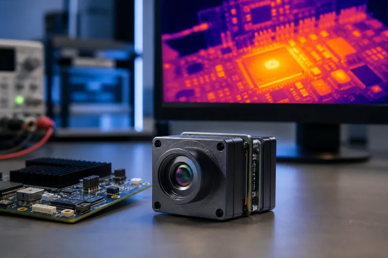
When you’re evaluating a cheap thermal imaging camera for an actual engineering build, you run headfirst into a classic fork in the road. On one side, you have sub-$500 handheld inspection gadgets and phone dongles made for quick spot checks around a jobsite. On the other side, you find uncooled Long-Wave Infrared (LWIR) OEM camera cores built from the ground up for embedded integration into automation rigs, robotic payloads, and industrial machine vision setups. Both tools detect thermal radiation in the 8 to 14 µm spectrum, but the similarity stops right at the surface. Under the hood, their detector chemistry, calibration drift profiles, optical modulation transfer functions (MTF), and interface latencies are worlds apart.
Here’s the deal: cutting through marketing hype requires looking straight past slogans like “software-enhanced clarity” or “super-resolution processing.” What actually dictates success on the bench comes down to physical hardware specs: microbolometer material, pixel pitch, Noise Equivalent Temperature Difference (NETD), Instantaneous Field of View (IFOV), and true native frame rates. Mounting a consumer-grade inspection tool inside an automated test fixture, an inspection drone, or a continuous process monitor almost always turns into an engineering headache marked by thermal drift, skipped anomalies, and driver lockups. This teardown walks through the physics of entry-level thermal imaging, weighs the trade-offs between handhelds and bare cores, and analyzes budget OEM solutions built for real-world integration.
Table of Contents
- 👉 The $200–$600 Dilemma: Consumer Gadget vs. Industrial Core Integration
- 👉 Understanding the Physics: Sensor Pitch, True Resolution, and NETD Sensitivity
- 👉 Refresh Rates & Temporal Latency: Why Budget Imagers Suffer from 9 Hz Choppiness
- 👉 Optical Selection & Spatial Resolution: Calculating Instantaneous Field of View (IFOV)
- 👉 Embedded Interface Protocols: SPI, USB UVC, MIPI CSI-2, and CVBS
- 👉 Engineering Comparison: Uncooled LWIR Cores vs. Handheld Units
- 👉 In-Depth OEM Product Evaluations: MD-64CA & TC160-NF
- 👉 Total Cost of Ownership (TCO): Hidden Costs of Consumer Handhelds
- 👉 OEM Procurement & Integration Roadmap: Step-by-Step RFQ Checklist
- 👉 Deep-Dive Technical FAQ
The $200–$600 Dilemma: Consumer Gadget vs. Industrial Core Integration
In the $200 to $600 price bracket, hardware architectures split down the middle. Handheld diagnostic imagers pack an entry-level microbolometer sensor (typically 80×60, 96×96, or 160×120 pixels) into a molded ABS enclosure alongside a low-res TFT display, an internal lithium-ion pouch cell, and hardcoded consumer firmware. These tools do fine for residential energy audits, quick HVAC checks, or identifying a tripped breaker in an electrical panel. They give a technician immediate visual confirmation on a colorized screen.
When you look at an uncooled OEM thermal camera core, the build philosophy is completely reversed. You strip away the plastic chassis, the cheap LCD screen, the tactile buttons, and the internal battery. Every dollar goes directly into the focal plane array (FPA), high-grade Germanium or Chalcogenide infrared optics, internal non-uniformity correction (NUC) shutters, and low-noise interface electronics. Consumer imagers often lean on edge-blending tricks to outline shapes using a secondary visible-light camera. That visual assist helps a human eye make sense of a fuzzy heat blotch, but it doesn’t give an automated machine vision system the raw 14-bit or 16-bit radiometric temperature arrays it needs to make autonomous pass/fail calls.
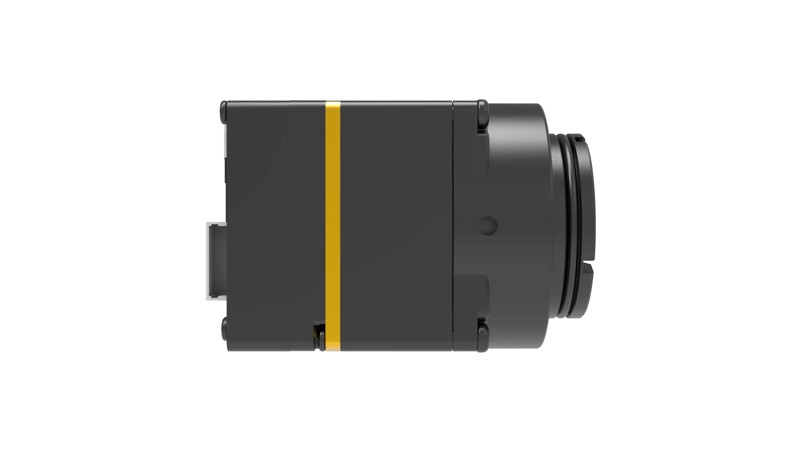
Closed firmware is another major hurdle with consumer gadgets. You can rarely extract raw radiometric matrices over USB; instead, you get an 8-bit visual color feed (like Ironbow or Rainbow) with burned-in overlays. Trapped inside a plastic housing with poor thermal dissipation, these units run hot when operated continuously, throwing off their baseline radiometric calibration. Bare OEM modules, on the other hand, provide direct metallic thermal transfer paths for active or passive heatsinking, run directly off industrial power buses (3.3V or wide 5–24V DC), and provide low-level register control for triggering calibration shutters on demand. If you’re deciding between a portable unit for technicians and an embedded sensor for equipment, check out our handheld thermal imaging camera field guide.
Understanding the Physics: Sensor Pitch, True Resolution, and NETD Sensitivity
Evaluating an affordable thermal imaging camera comes down to fundamental physics. Because long-wave infrared radiation (8 to 14 µm) obeys Planck’s and the Stefan-Boltzmann laws, a microbolometer array must absorb incoming photons and convert that energy into measurable resistance changes across its pixel matrix without drowning in electronic noise.
1. Detector Chemistry: Vanadium Oxide (VOx) vs. Amorphous Silicon (a-Si)
Uncooled microbolometers are generally built with either Vanadium Oxide (VOx) or Amorphous Silicon (a-Si). In production environments, VOx has become the gold standard. It delivers a high Temperature Coefficient of Resistance (TCR)—typically around -2% to -3% per Kelvin—paired with low 1/f flicker noise. This lets engineers build smaller 12 µm pixels while maintaining high sensitivity. Amorphous silicon, while cheaper to process in standard fabs and common in ultra-budget tools, usually requires larger 17 µm to 35 µm pixels to collect enough photons, and it suffers from elevated thermal noise when ambient temperatures fluctuate.
2. True Native Resolution vs. Software Upscaling
Watch out for datasheets quoting “interpolated resolution.” Software upscaling cannot synthesize missing spatial data. Spatial resolution is locked to the physical detector pixel count on the focal plane array:
⚙️ 160 × 120 (19,200 active pixels): Baseline resolution. Perfect for close-up PCB thermal profiling, localized HVAC vent balancing, and industrial human presence detection.
⚙️ 384 × 288 (110,592 active pixels): Balanced middle ground. Great for plant maintenance, electrical panel inspections, and compact conveyor monitoring systems.
⚙️ 640 × 512 (327,680 active pixels): The industrial standard. Delivers the spatial clarity needed for pinpointing failing 0402 surface-mount components, automated optical gas imaging, process lines, and long-range perimeter tracking.
3. Noise Equivalent Temperature Difference (NETD)
NETD defines the lowest temperature variation a sensor can distinguish above its own internal noise floor. Expressed in millikelvins (mK) at a specific optical aperture (typically F/1.0), lower numbers mean higher sensitivity:
🔍 ≤30 mK (Industrial Grade): Picks up subtle thermal shifts down to 0.03°C. Essential for spotting moisture intrusion in building envelopes, tiny mechanical friction points, and early semiconductor junction degradation.
🔍 ≤50 mK to 70 mK (Mid-Tier Prosumer): Standard on solid handheld tools like those from Hikmicro. Reliable for identifying general electrical overloads and mechanical hotspots.
🔍 >100 mK (Ultra-Budget Tier): Found on entry-level phone attachments. When looking at low-contrast targets at ambient room temperature, the stream turns noisy and grainy, masking critical thermal details.
Refresh Rates & Temporal Latency: Why Budget Imagers Suffer from 9 Hz Choppiness
If you’ve ever panned a cheap thermal imaging camera across a workspace, you’ve probably noticed annoying display lag and stuttering. That sluggishness comes down to two bottlenecks: dual-use export limits and the physical thermal time constant of the sensor membrane.
Under international export controls like the Wassenaar Arrangement, thermal cameras running at or above 9 Hz are classified as dual-use goods because of their potential use in weapon systems and surveillance. To sell globally without requiring complicated export paperwork for every consumer transaction, manufacturers artificially lock firmware to 8.8 Hz or 9 Hz. When you sweep a 9 Hz camera across a live electrical cabinet, the image tears and blurs. High-speed thermal transients vanish between frames, and automated tracking loops fall apart due to spatial lag.
Then you have the thermal time constant (tau) of the microbolometer itself. Each pixel consists of an infrared-absorbing bridge suspended above a silicon readout integrated circuit (ROIC). The membrane has to absorb incoming LWIR energy, change temperature and resistance, and dissipate that heat to the substrate before reading the next frame. Industrial VOx sensors feature thin, low-mass membranes with thermal time constants of 8 to 12 ms, easily sustaining 25 Hz to 50 Hz frame rates with zero ghosting. In contrast, cheap a-Si sensors often have time constants pushing past 15 to 20 ms, which creates physical hardware lag that software updates can’t fix.
For automated optical inspection (AOI), conveyor sorting, robotics, and drone payloads, running a native 25 Hz or 50 Hz OEM core ensures frame-to-frame latencies stay under 20 ms without motion artifacts.
Optical Selection & Spatial Resolution: Calculating Instantaneous Field of View (IFOV)
Standard optical glass acts like a solid wall to long-wave infrared light. Thermal lenses must be precision-machined from specialized materials like monocrystalline Germanium (Ge), Chalcogenide glass, or Zinc Selenide (ZnSe). Germanium provides exceptional transmission across 8–14 µm with a high refractive index, though it carries a premium price tag. Chalcogenide glass gives engineers an economical, moldable alternative for budget OEM assemblies without sacrificing optical sharpness.
Instantaneous Field of View (IFOV) and Target Resolution
Spatial resolving power depends on detector pixel pitch (d) and lens focal length (f):
IFOV (in milliradians) = Pixel Pitch (µm) / Optical Focal Length (mm)
To find the physical spot dimension (S) covered by a single pixel at a specific working distance (D):
Spot Dimension (S) = IFOV (mrad) × Target Distance (m)
To get an accurate, calibrated temperature reading (Measurement IFOV or MFOV), an anomaly needs to cover at least a 3×3 pixel cluster—and ideally 4×4 pixels. This prevents optical blur around the edges (governed by the system’s Point Spread Function) from bleeding background ambient temperatures into your measurement pixel.
For long-range surveillance and perimeter defense, narrow-field optics are necessary to resolve targets kilometers away, as seen in setups like the URA-Y Series 640×512 observation binocular. For embedded rigs, selecting the right factory-matched focal length ensures your spatial resolution matches the mechanical constraints of your inspection bay.
Embedded Interface Protocols: SPI, USB UVC, MIPI CSI-2, and CVBS
When wiring a bare thermal core into an embedded host, your interface choice determines processing overhead, bus bandwidth, and firmware complexity:
⚙️ Serial Peripheral Interface (SPI): Operates as a 4-wire synchronous bus (SCLK, MOSI, MISO, CS) clocked between 10 MHz and 40 MHz. Excellent for low-power MCUs (STM32, ESP32, NXP i.MX RT) reading compact 160×120 arrays without needing a dedicated video pipe.
⚙️ USB Video Class (USB UVC): Built on standard USB architectures detailed in the USB 3.2 Specification. UVC is plug-and-play across Linux (V4L2), Windows, Android, and macOS. It allows SBCs (Raspberry Pi, Jetson Nano, x86 platforms) to capture raw 14-bit radiometric matrices (Y16 format) directly into OpenCV, ROS, or custom C++ computer vision code.
⚙️ MIPI CSI-2: Sends differential video streams straight into the host processor’s Image Signal Processor (ISP). Bypassing USB transceiver overhead, MIPI CSI-2 is the top pick for weight-critical drone gimbals and edge-AI camera assemblies needing direct memory access (DMA).
⚙️ CVBS (Composite Video Baseband Signal): Standard 75-ohm analog video (PAL/NTSC). CVBS provides reliable, sub-20 ms analog video for FPV monitors, legacy security systems, and cockpit screens without operating system boot times.
Engineering Comparison: Uncooled LWIR Cores vs. Handheld Units
The engineering comparison below evaluates two production-grade OEM modules against a typical entry-level handheld inspection tool:
| Specification | Camcuda TC160-NF Bare Core | Camcuda MD-64CA OEM Module | Typical Sub-$400 Consumer Handheld |
|---|---|---|---|
| Detector Type | Uncooled LWIR Module | Uncooled VOx Focal Plane Array | Amorphous Silicon (a-Si) Array |
| Native Resolution | 160 × 120 (19,200 px) | 640 × 512 (327,680 px) | 80 × 60 to 160 × 120 px |
| Pixel Pitch | 35 µm reference | 12 µm | 17 µm – 35 µm |
| NETD Sensitivity | ≤50 mK class | ≤30 mK reference | >60 mK to 100 mK |
| Max Frame Rate | Up to 25 FPS | 50 Hz Output | Capped at ≤9 Hz |
| Host Interfaces | SPI (10-pin FPC, 0.5mm pitch) | USB UVC, MIPI, or CVBS | Proprietary USB-C / App only |
| Supply Voltage | 3.3 V DC | 5 – 24 V Wide Input | Internal 3.7V Li-ion Battery |
| Power Draw | ~76 – 78 mW | <0.7 W reference | 1.5 W – 3.0 W (with screen) |
| Module Weight | Ultra-lightweight (<10 g) | 23.1 g | 300 g – 550 g |
| Operating Temp | -20°C to +85°C | -20°C to +60°C | -10°C to +45°C |
| Price Level | Low-cost embedded tier | From $475.00 | $299.00 – $399.00 |
In-Depth OEM Product Evaluations: MD-64CA & TC160-NF
For engineering teams integrating thermal vision into hardware assemblies, these two bare-module platforms deliver industrial reliability without enterprise-level price tags.
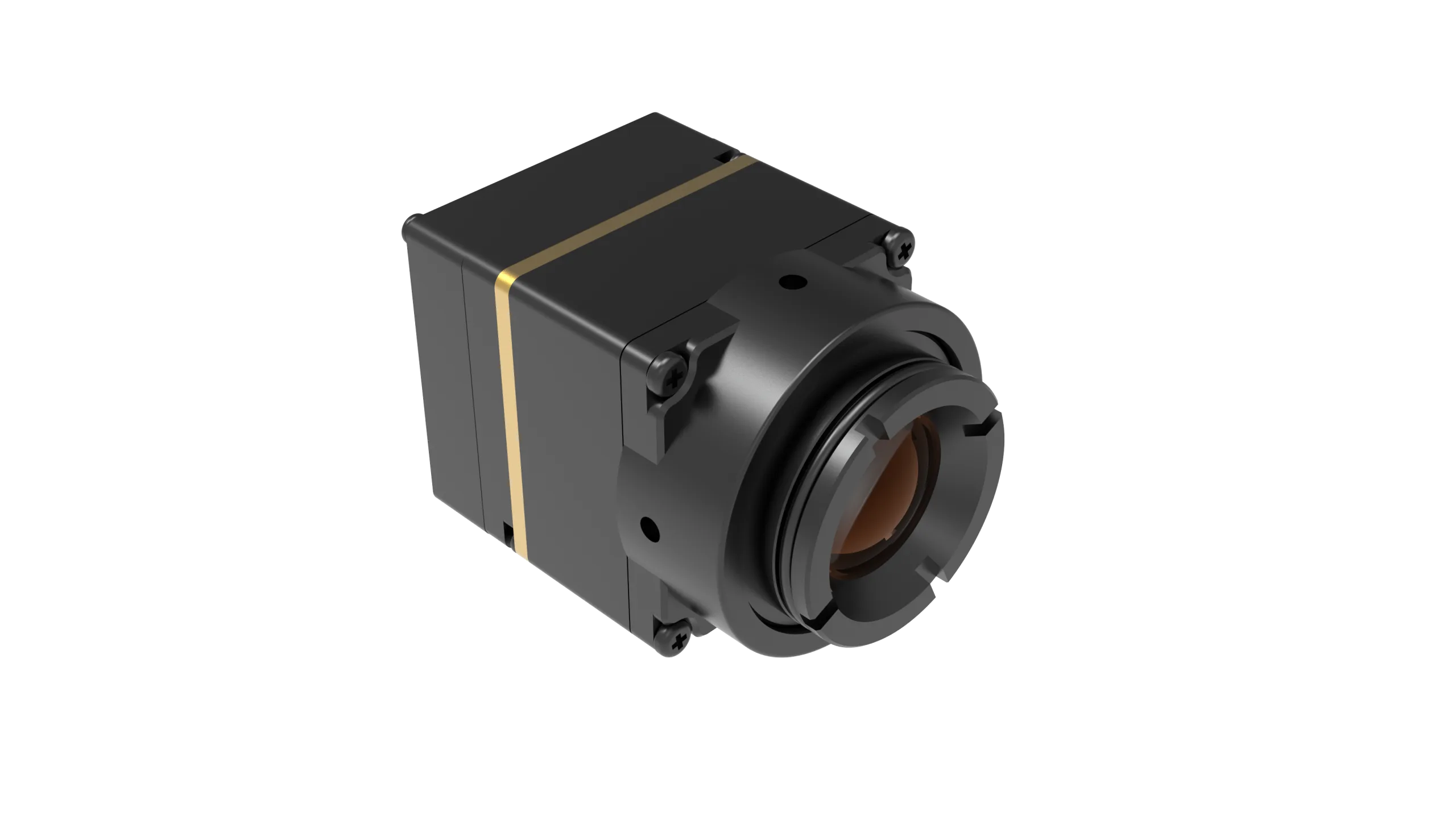
1. MD-64CA 640 x 512 Uncooled VOx Thermal Imaging Camera Module
MD-64CA Core Specifications & Features
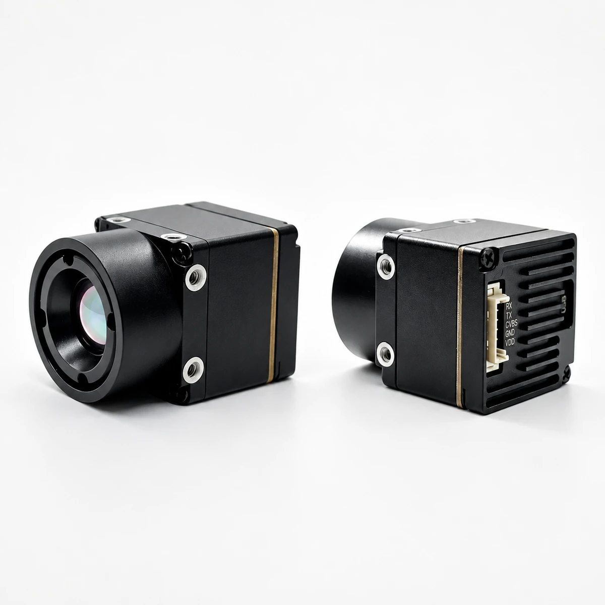
The MD-64CA module combines a dense 640 × 512 uncooled Vanadium Oxide (VOx) focal plane array, a tight 12 µm pixel pitch, ≤30 mK NETD sensitivity, and a smooth 50 Hz frame rate into an ultra-compact 23.1 g housing. Engineered for robotics builders, instrumentation designers, and vision integrators, it accepts wide 5–24 V DC power inputs while drawing under 0.7 W.
- ✅ Native Resolution: 640 × 512 pixels (12 µm pitch)
- ✅ Thermal Sensitivity: ≤30 mK NETD reference for minute differential detection
- ✅ Aperture & Band: F1.0 optical aperture, 8–14 µm LWIR spectral response
- ✅ Video Latency: <20 ms latency with automated NUC calibration and PAL timing
- ✅ Interface Options: Factory selectable CVBS analog, USB UVC, or MIPI digital streams
Factory-Fitted Lens Configuration Options
The MD-64CA uses factory-aligned precision optics, calibrated during assembly to hold optical alignment and focus across wide operating temperatures:
| Focal Length | Field of View (FOV) | IFOV | Unit Price | Stock Status |
|---|---|---|---|---|
| 9.1 mm | 45.8° × 37.3° | 1.31 mrad | $475.00 | In Stock (Standard) |
| 4.9 mm | 76.2° × 64.2° | 2.45 mrad | $522.50 | In Stock (+10%) |
| 4.1 mm | Extra-Wide Angle | Confirmed with Quote | $522.50 | In Stock (+10%) |
| 13 mm | 33.0° × 26.6° | 0.92 mrad | $522.50 | Volume RFQ Restock |
| 19 mm | 22.9° × 18.4° | 0.63 mrad | $522.50 | Volume RFQ Restock |
| 35 mm | 12.5° × 10.0° | 0.34 mrad | $522.50 | Volume RFQ Restock |
Target Range Estimation (Johnson Criteria: 1.8m × 0.5m Human Target)
| Lens | IFOV | Detection Range | Recognition Range | Identification Range |
|---|---|---|---|---|
| 4.9 mm | 2.45 mrad | 476.00 m | 119.00 m | 60.00 m |
| 9.1 mm | 1.31 mrad | 884.72 m | 221.18 m | 110.59 m |
| 13 mm | 0.92 mrad | 1,263.89 m | 315.97 m | 157.99 m |
| 19 mm | 0.63 mrad | 1,847.22 m | 461.81 m | 230.90 m |
| 35 mm | 0.34 mrad | 3,402.78 m | 850.69 m | 425.35 m |
Interface Pinout Planning
Confirm your physical connector setup before laying out host PCB traces:
- ⚙️ USB UVC Connector: USB-VDD, D-, D+, GND
- ⚙️ CVBS Analog Connector: Rx, Tx, CVBS, GND, VCC
- ⚙️ Operating Temperature: Rated from -20°C to +60°C
View Product Details & Pricing ➔
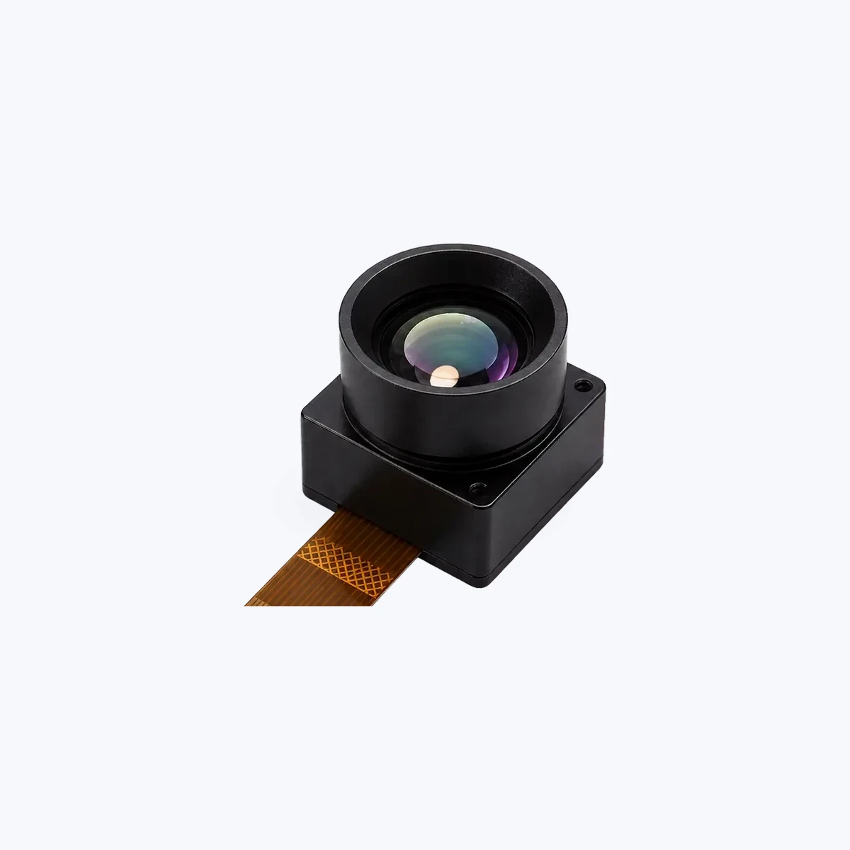
2. TC160-NF 160×120 Uncooled LWIR Thermal Imaging Module
TC160-NF Core Specifications & Embedded Fit
The TC160-NF (SKU: MI1602M5S) is an ultra-low-power uncooled LWIR core tailored for smart home devices, HVAC airflow diagnostics, and battery-backed IoT edge sensor nodes. Built around a 10-pin FPC connector with a 0.5 mm pitch, this core sips just 76 to 78 mW at 3.3 V DC, making it ideal for remote or power-constrained enclosures.
- ✅ Resolution: 160 × 120 (19,200 active pixels, 35 µm detector pitch)
- ✅ Spectral Band: 8–14 µm LWIR with factory-calibrated radiometric output
- ✅ Optical FOV: Narrow-angle lens (56° Diagonal / 45° Horizontal / 34° Vertical)
- ✅ Frame Rate: Up to 25 FPS for smooth temporal tracking
- ✅ Host Interface: SPI synchronous bus (USB evaluation board available)
- ✅ Extended Temp: Industrial operational rating from -20°C to +85°C
Application Fit Matrix
- ⚙️ Smart Kitchen Appliances: Delivers non-contact thermal tracking without visual privacy concerns.
- ⚙️ HVAC & Occupancy Sensing: Monitors heat stratification, duct efficiency, and room occupancy with negligible CPU overhead.
- ⚙️ Perimeter Gates & Access: Concentrates pixels across narrow corridors and automated entryways.
- ⚙️ Edge AI Wake-Up: Acts as an ultra-low-power thermal trigger to wake up high-draw machine vision cameras and edge processors.
View Product Details & Pricing ➔
Total Cost of Ownership (TCO): Hidden Costs of Consumer Handhelds
When selecting a cheap thermal camera for production machinery or continuous test rigs, looking only at the initial sticker price is a fast way to blow your engineering budget. Consumer units carry hidden lifecycle costs that quickly show up once deployed in the field.
1. Driver Reverse-Engineering and Firmware Breakage
Consumer dongles rarely provide stable C/C++ SDKs, direct Linux kernel support, or clean V4L2 hooks. Integrating a phone-based dongle into an automated test station usually forces your software engineers to scrape screens, run unstable Android emulators, or reverse-engineer raw USB descriptors. When the manufacturer pushes a proprietary app update or alters firmware, your data pipeline breaks. Standard UVC, SPI, and MIPI OEM modules eliminate this headache by streaming clean data straight into native OS video stacks.
2. Battery Degradation in 24/7 Operation
Consumer handheld cameras run on internal lithium-ion pouch cells meant for occasional field use. If you leave them permanently plugged into a 5V USB charger inside an industrial cabinet, the battery stays pegged at 100% in continuous float-charge. Within 6 to 12 months, that cell will swell, degrade, cause spontaneous system resets, or present a fire hazard. Bare OEM modules omit internal batteries completely, drawing direct, reliable power from industrial 3.3V or wide 5–24V DC rails.
3. False Yields from Spot-Size Bleed (PSF)
Using an entry-level 80×60 consumer camera for PCB thermal screening leads to massive measurement errors. If a tiny SMD regulator is cooking at 115°C but its physical footprint covers only a fraction of a pixel, the camera blends that hotspot with the surrounding 30°C ground plane, reading out a false 70°C. That missed failure can lead to field recalls that dwarf the initial savings of a cheap sensor.
OEM Procurement & Integration Roadmap: Step-by-Step RFQ Checklist
To avoid expensive hardware revisions down the line, engineering teams must lock in their optical, mechanical, and electrical parameters before freezing system schematics. For a deeper breakdown of supplier validation, consult our thermal camera suppliers OEM RFQ checklist.
Before submitting a Request for Quotation (RFQ) for OEM modules like the MD-64CA or TC160-NF, have these five engineering requirements clearly documented:
- Target Size & Working Distance: Define the smallest critical anomaly size (S) and your working distance (D). Make sure your selected lens satisfies Measurement IFOV (at least 3×3 pixels covering the target).
- Factory Lens Specification: Select the correct focal length upfront (e.g., 4.9 mm, 9.1 mm, 13 mm, 19 mm, or 35 mm for the MD-64CA). OEM thermal lenses are aligned and calibrated at the factory; they cannot be adjusted in the field without ruining radiometric accuracy.
- Hardware Interface Selection: Confirm whether your host architecture requires USB UVC (driverless V4L2/Windows), SPI (direct MCU register access), MIPI CSI-2 (low-overhead DMA video), or CVBS (analog composite).
- Power & Thermal Dissipation: Verify your power supply rails (3.3V for TC160-NF, 5–24V for MD-64CA) and design your housing to sink heat away from the core, keeping internal temps within rated operating limits (-20°C to +60°C / +85°C).
- Data Stream Output: Decide whether your software pipeline needs processed 8-bit visual color palettes or true 14-bit radiometric matrices (Kelvin/raw counts) for automated machine vision algorithms.
Deep-Dive Technical FAQ
Are cheap thermal cameras under $400 actually worth buying for technical inspections?
Why do many budget thermal cameras feel laggy and have choppy video?
What is the practical difference between a cheap standalone imager and an OEM thermal module?
📚 References & Further Reading
- Industry Standard: USB 3.2 Specification & UVC Video Framework
- Thermal Inspection Tech: Hikmicro Commercial Thermal Solutions
- Related Buying Guide: Handheld Thermal Imaging Camera Field Buying Guide
- OEM Procurement Guide: Thermal Camera Suppliers OEM RFQ Checklist
- Long-Range Binocular Reference: URA-Y Series 640×512 Handheld Observation Binoculars