Infrared Camera Module: 9 Proven Checks for Reliable OEM Design
Infrared camera module buying becomes difficult when a team compares product photos instead of integration requirements. A useful module choice should answer a practical question: will this thermal core fit the aircraft, enclosure, host board, software workflow, and inspection task without forcing a redesign after samples arrive?
Technical author: Daniel · Hardware Support
Quick answer: use the module as a system decision, not a single spec.
Start with CAMCUDA AeroMini 640 for configurable OEM integration: 640 × 512 uncooled VOx, 12 μm pixel pitch, 60 Hz factory-default imaging with a 30 Hz factory option, and ≤30 mK NETD at 25°C, F/1.0. Its published 21 × 21 × 28 mm envelope and <20 g weight exclude the lens and flange; <0.5 W is module consumption at 25°C, not complete-kit power. Compare SuperMini 640 when the core envelope is tighter, then confirm the selected interface board, lens and host workflow.
- Use this guide if you are building a drone payload, OEM embedded system, outdoor thermal device, or machine vision prototype.
- Use the tables below as a quick-reference chart before requesting a quote.
- Use the FAQ section to address buyer questions collected from drone and thermal-imaging communities.
Infrared camera module selection chart
The chart below turns product parameters into buying decisions. This is the part most thin SEO articles miss: a buyer does not only need to know that a module is 640 × 512; they need to know when that value matters and what else must be checked with it.
| Buyer situation | Best first question | Current module value to check | Decision signal |
|---|---|---|---|
| Drone thermal payload | Can the aircraft carry it without hurting flight time or stability? | AeroMini: <20 g and 21 × 21 × 28 mm, excluding lens and flange; <0.5 W module power at 25°C; 60 Hz default / 30 Hz factory option | Validate the complete lens, board, mount and host-video assembly before committing the payload budget. |
| Solar / electrical inspection | Will the image reveal useful thermal contrast at the planned distance? | Both: 640 × 512, 8–14 μm. NETD at 25°C, F/1.0: AeroMini ≤30 mK; SuperMini ≤40 mK | Validate lens/FOV and inspection procedure. Temperature reporting requires a separately specified thermographic version. |
| OEM embedded device | Can the host board and software accept the interface? | AeroMini: USB + CVBS + MIPI or Type-C + CVBS kits; UART / RS232 / RS422 and supply input depend on the board | Ask for the selected board’s wiring, voltage and host-software notes before enclosure tooling. |
| Outdoor field observation | Can the system survive climate and motion? | AeroMini: −40°C to +80°C. SuperMini imaging: −40°C to +70°C. Both: 5–95% non-condensing humidity | These are module limits, not enclosure protection or thermographic-condition guarantees. Request assembly-specific vibration and shock evidence. |
| Low-cost prototype | Is the cheap sensor enough for the real task? | Compare resolution, frame rate, NETD, output path, and documentation depth | A low-cost infrared camera module can teach basics, but production RFQs need stable specs and support. |
Infrared camera module parameter table for AeroMini and SuperMini
The following chart uses the current CAMCUDA product pages linked above. AeroMini is the primary reference; SuperMini is the compact-core comparison. Confirm the exact model, board revision, lens, firmware and sample availability in the RFQ. A parent product listing does not guarantee stock or lead time for every configuration.
| Selection area | Parameter | Current product reference / confirmation needed | How to use it in an RFQ |
|---|---|---|---|
| Model identity | Component model | Primary: AeroMini 640. Comparison: SuperMini 640 imaging; SuperMini 640T thermographic | Use the exact model and configuration when requesting drawings, interface support, price or sample availability. |
| Detector platform | Detector type | Both: uncooled vanadium oxide (VOx) | Both are LWIR integration cores; confirm the complete assembly. |
| Image detail | Resolution | Both: 640 × 512 | Match lens/FOV and target distance to the required scene detail. |
| Motion/video | Imaging frame rate | AeroMini: 60 Hz factory default; 30 Hz factory option. SuperMini 640: 50 Hz | Imaging-only rates. Confirm the frame rate available on the selected output, firmware and host; thermographic versions are separate. |
| Optical matching | Pixel pitch | AeroMini: 12 μm. SuperMini: 8 μm | Use each model’s lens/FOV data; equal focal lengths do not produce equal fields of view. |
| Thermal band | Spectral range | Both: 8–14 μm | Check that the lens and enclosure window are suitable for LWIR transmission. |
| Sensitivity | NETD | AeroMini: ≤30 mK. SuperMini: ≤40 mK. Both at 25°C, F/1.0 | Compare the stated test conditions and validate thermal contrast in the intended scene; NETD is not a temperature-accuracy specification. |
| Image tuning | Brightness / contrast / enhancement | Confirm available controls and adjustment ranges for the selected model and firmware | Do not assume identical tuning controls or ranges across models. |
| Operator display | Pseudo color palettes | Confirm the palette list for the selected model and firmware | Choose palettes around the operator workflow; do not rely on color alone for measurement claims. |
| Image quality | Non-uniformity correction | Confirm the selected model’s correction method and control commands | Test image continuity and correction behavior across scene and temperature changes. |
| Noise control | Temporal filtering | Confirm availability and controls for the selected model and firmware | Test the tradeoff between video stability and motion detail in the intended scene. |
| Noise control | Spatial filter noise reduction | Confirm availability and controls for the selected model and firmware | Check visual clarity and retained target detail rather than assuming identical processing between models. |
| Detail perception | Digital detail enhancement | Confirm availability and controls for the selected model and firmware | Evaluate equipment outlines and thermal anomalies using the chosen image settings. |
| Scene presentation | Histogram brightness adjustment | Confirm the selected model’s brightness-control behavior | Test representative scene temperature ranges before fixing the operator workflow. |
| Power design | Supply voltage | AeroMini: 5 V or 12 V, board-dependent; documented POWER_IN1 / POWER_IN2 pins are 5 V only. SuperMini: MAIN_POWER 3.8–5.2 V plus separate 3.3 V and 1.8 V rails | Do not apply 12 V to AeroMini’s documented 5 V inputs. Confirm rail tolerances, noise limits and power-on timing for the ordered hardware. |
| Power design | Typical power consumption at 25°C | AeroMini: <0.5 W module consumption. SuperMini: ≤0.5 W core consumption, excluding expansion board | AeroMini complete-kit consumption may differ. Add boards, host processing and transmission hardware to the system budget. |
| Video path | Digital video | AeroMini: USB + CVBS + MIPI or Type-C + CVBS kits. SuperMini: 8-bit LVCMOS / BT656 and 2-lane MIPI; optional USB expansion board | Confirm the receiver, format and timing. SuperMini BT656 and MIPI cannot operate simultaneously; its CVBS signal requires an external video-buffer IC. |
| Control path | Communication interface | AeroMini: UART, RS232 or RS422, board-dependent. SuperMini: UART with 1.8 V logic | Match the command protocol and electrical levels; video and control are separate integration checks. |
| Payload fit | Published weight | AeroMini: <20 g, excluding lens and flange. SuperMini: <3.5 g, excluding lens, flange and user expansion board | These different measurement scopes are not complete installed-payload weights. |
| Mechanical fit | Published dimensions | AeroMini: 21 × 21 × 28 mm, excluding lens and flange. SuperMini: 13 × 13 × 13.4 mm, excluding lens, flange and user expansion board | Use the configured assembly drawing for enclosure, mounting and cable clearance. |
| Outdoor use | Operating temperature | AeroMini: −40°C to +80°C. SuperMini imaging: −40°C to +70°C | These are module operating limits, not an enclosure IP rating. Confirm thermographic conditions separately. |
| Storage/logistics | Storage temperature | Request the storage specification for the selected model and assembly | Confirm shipping and warehousing limits; do not transfer another model’s storage rating. |
| Environment | Humidity | Both: 5–95%, non-condensing | A non-condensing humidity range does not establish rain resistance; validate enclosure sealing and condensation control. |
| Ruggedization | Vibration | Request qualification evidence for the selected core, board and complete assembly | Review the intended UAV, vehicle or robotics mount; do not inherit another model’s vibration rating. |
| Ruggedization | Shock | Request qualification evidence for the selected core, board and complete assembly | Validate handling, transport and field-use requirements; do not inherit another model’s shock rating. |
Version boundary: AeroMini radiometric is a separate 25 Hz version, currently available for supply enquiries only. SuperMini 640T is the separate 30 Hz thermographic model. Confirm the temperature-data output, lens, interface and thermographic operating conditions independently; the imaging-only versions above do not measure temperature.
Drone use case: solar farm and power equipment inspection
Scenario
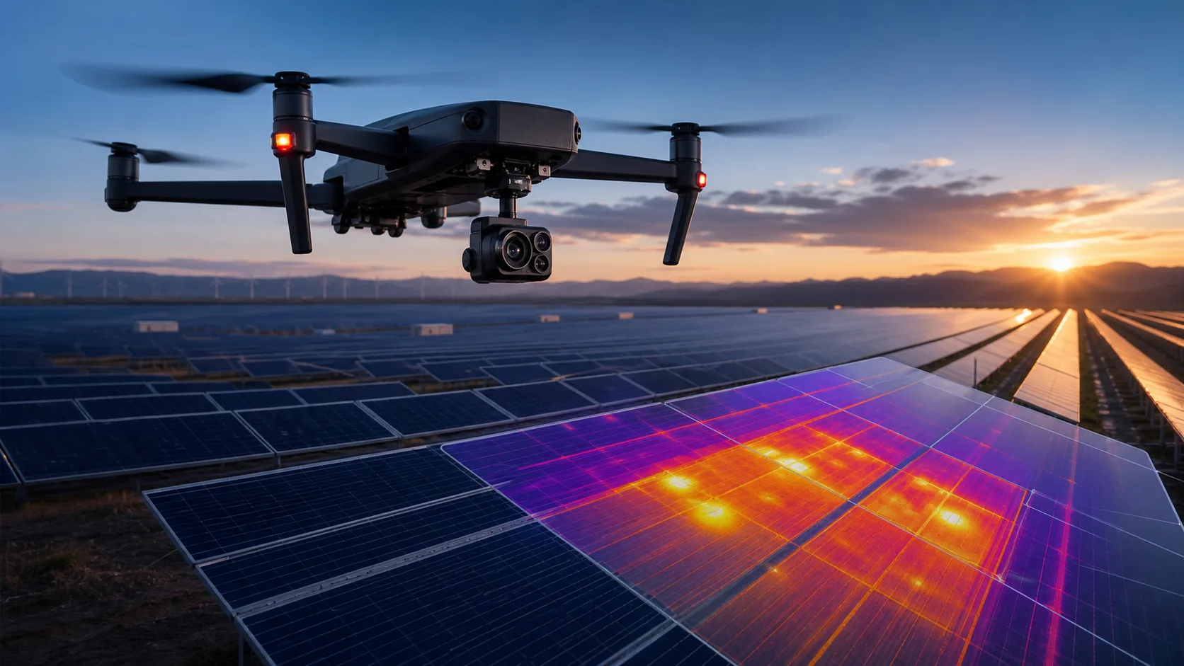
A UAV integrator wants to build a lightweight thermal inspection payload for solar farms, roof-mounted arrays, substations, and power equipment. The team needs thermal video that can reveal hot spots and equipment anomalies, but the aircraft cannot carry a heavy payload and the software team needs a practical video path.
How the AeroMini values affect the decision
- <20 g published weight excludes the lens and flange; budget the complete payload separately.
- <0.5 W module consumption at 25°C is a starting point; add the interface board, host and transmission hardware.
- 640 × 512 resolution must be matched to lens/FOV, flight height and target size.
- ≤30 mK NETD at 25°C, F/1.0 describes thermal sensitivity under stated test conditions, not temperature-measurement accuracy.
- 60 Hz default / 30 Hz factory-option imaging still requires validation on the selected output and host.
- Board-dependent USB video can support early evaluation when the chosen kit, drivers and software are matched.
The conclusion is not “buy this for every drone.” The conclusion is: this module deserves an RFQ review when your UAV project needs compact 640 × 512 LWIR output and you can define flight height, target distance, lens/FOV, host platform, and reporting workflow.
Use the CAMCUDA thermal imaging calculator to estimate DRI, IFOV, field of view and scene coverage for the selected detector, lens and working distance. These are geometric planning estimates, not guarantees of actual detection performance or temperature-measurement accuracy. Validate the complete inspection system in the intended conditions.
What Reddit buyer questions reveal about the market
Brave Search results from Reddit discussions show that real buyers and pilots often ask about pricing solar thermal inspections, thermal inspection tips for solar plants, whether pilots are offering thermal services, and how USB or high-resolution modules behave in real-time streaming workflows. The pattern is clear: they are not only asking “which camera?” They are asking about deliverables, workflow, interface, standards, altitude, reporting, and whether thermal work can become a real business.
For broader thermal-imaging terminology and industrial thermography context, buyers can compare their requirements with the ISO 18434-1 thermography standard page. That is why an infrared camera module article should include tables, cases, and RFQ checklists. The best buyer does not want a generic definition. They want to avoid choosing the wrong module before a product, payload, or inspection workflow is defined.
In short, an infrared camera module should be evaluated like a system component. The same infrared camera module can be a strong fit for one UAV inspection workflow and a poor fit for another enclosure if the interface, lens, and reporting path are different.
Infrared camera module USB and RS-422 interface planning
AeroMini interface planning starts with the selected USB + CVBS + MIPI or Type-C + CVBS board; UART, RS232 and RS422 availability depends on that board. SuperMini is a different core-integration path with 1.8 V UART and an optional USB expansion board. Confirm video, control and power before enclosure tooling, host-board routing or software scheduling; use the board-specific references below for the corresponding hardware.
| Integration check | Scope | Current product reference | Integration note |
|---|---|---|---|
| Power input | AeroMini board; SuperMini core rails | AeroMini supply depends on the board; documented POWER_IN1 / POWER_IN2 are 5 V only. SuperMini MAIN_POWER is 3.8–5.2 V plus separate 3.3 V and 1.8 V rails | Never apply 12 V to AeroMini’s documented 5 V pins. Confirm the selected assembly’s power sequence and limits. |
| Video output | Board / host receiver | AeroMini: USB + CVBS + MIPI or Type-C + CVBS kits. SuperMini: BT656 or 2-lane MIPI; optional USB expansion board | SuperMini BT656 and MIPI cannot operate simultaneously; CVBS requires an external video-buffer IC. Confirm data format and timing. |
| Control path | Protocol / electrical level | AeroMini: UART, RS232 or RS422, board-dependent. SuperMini: 1.8 V UART | Match host levels and command protocol; a control port is not a video-output guarantee. |
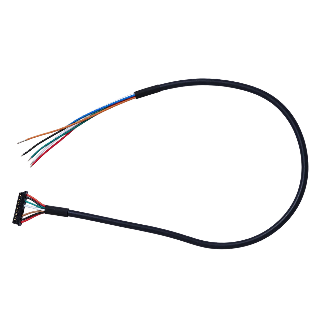
| Connector and cable | Matched assembly documentation | Request the exact board revision, connector orientation and cable drawing | AeroMini’s USB + CVBS + MIPI cable requires customer soldering; use the separate guide for Type-C hardware. Do not reuse HR21 wiring. |
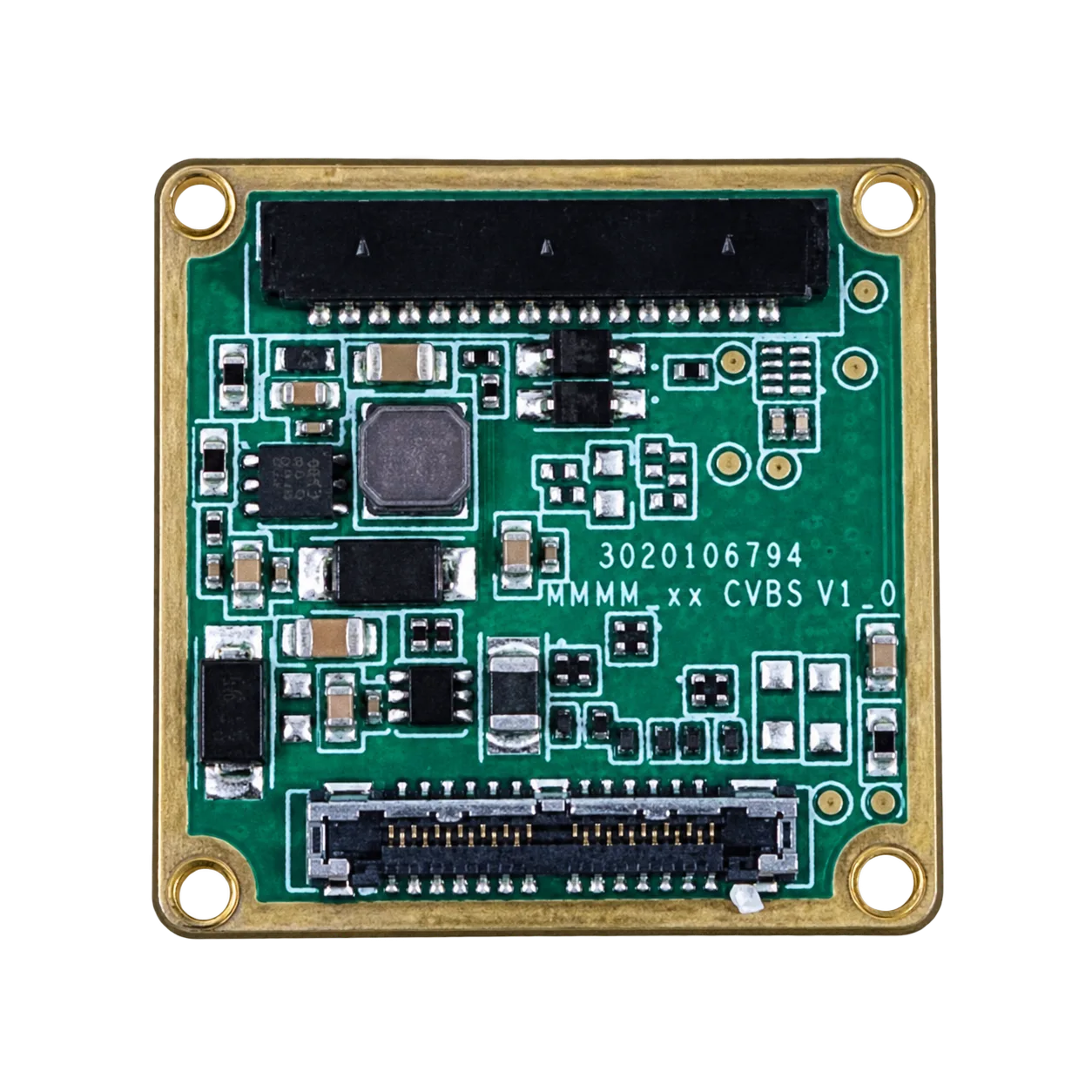
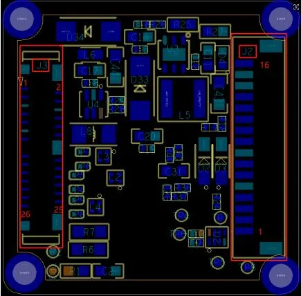
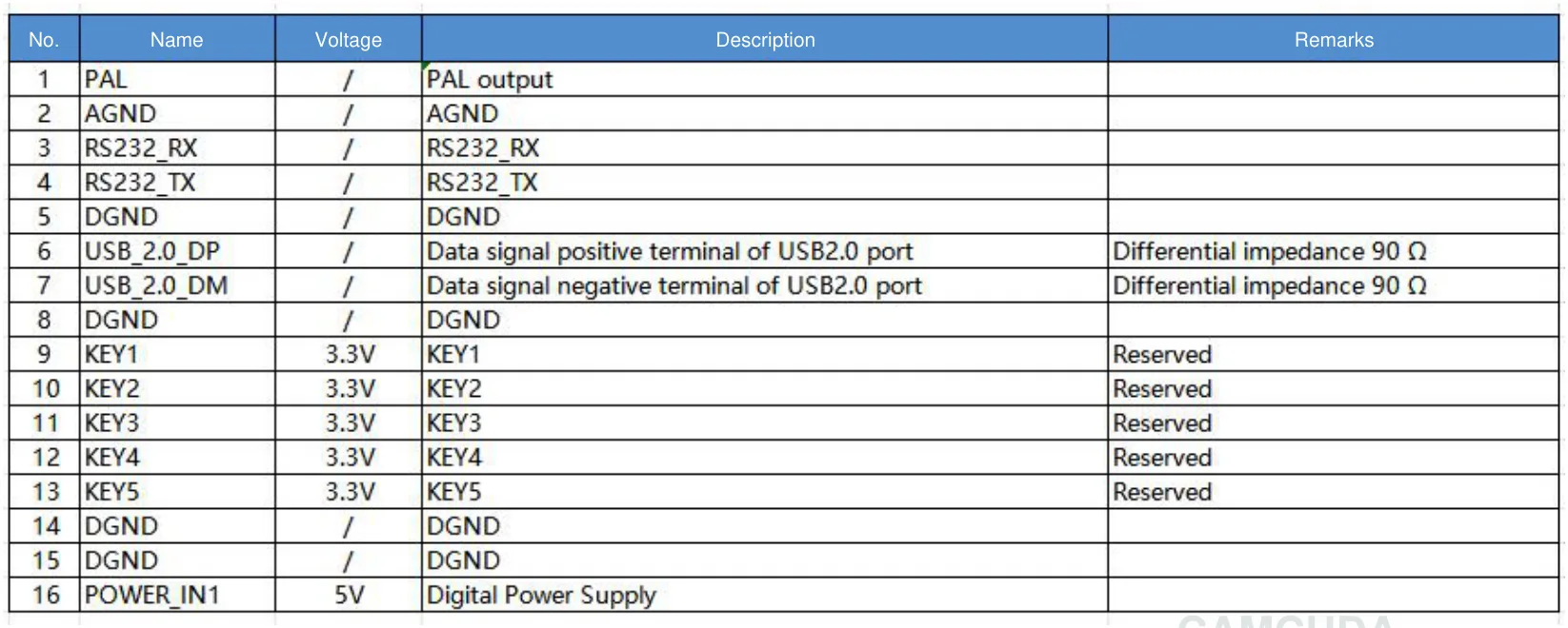
AeroMini USB + CVBS + MIPI board: compare the actual tailboard photograph and illustrated interface-board layout with the supplied hardware before selecting a connector reference.

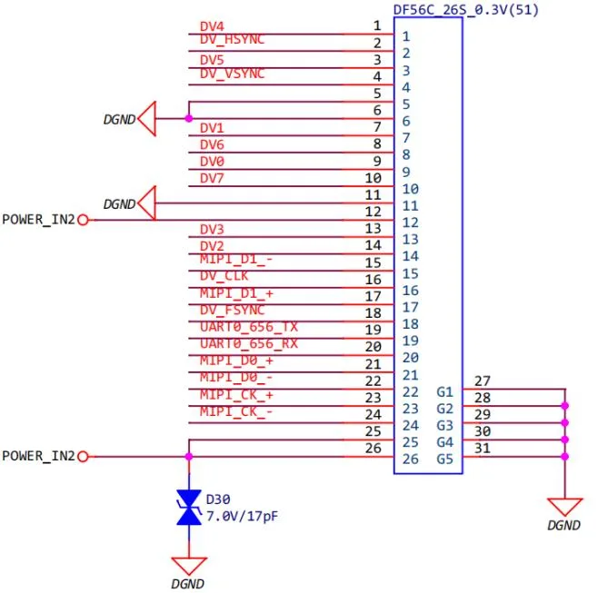
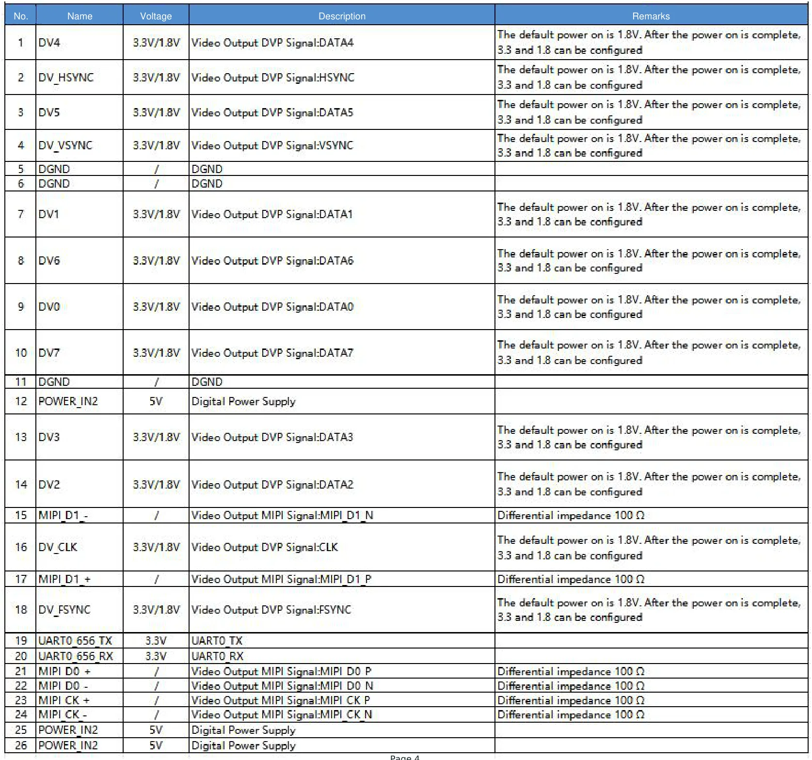
For the MIPI/DVP connector on the illustrated USB + CVBS + MIPI board, use the official 26-pin electrical schematic with the complete 26-pin signal table. POWER_IN2 is also a 5 V input. These 16-pin and 26-pin references apply only to the matched illustrated board, not to the Type-C board. Both the 16-pin and 26-pin diagrams are electrical schematics, not physical mating views.
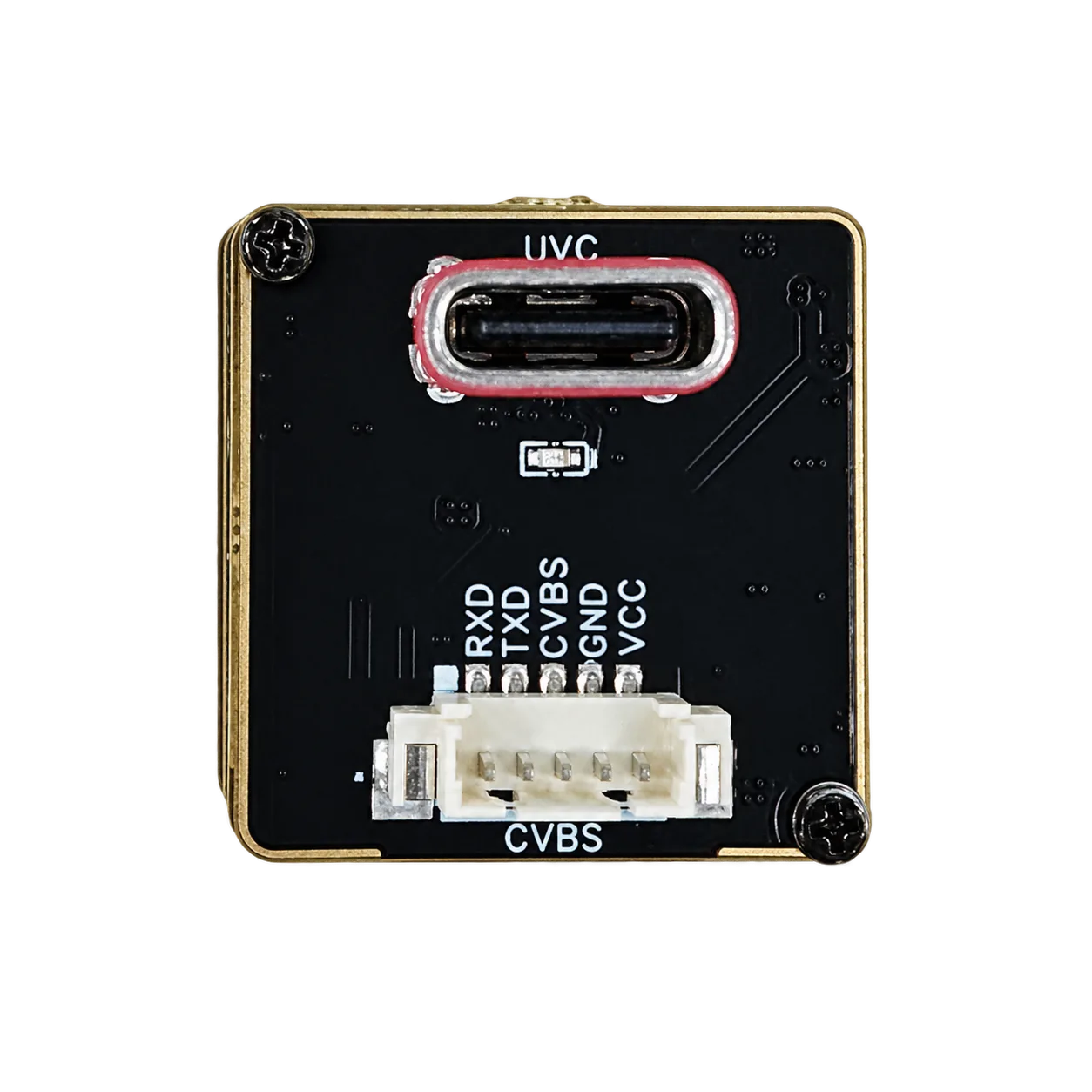
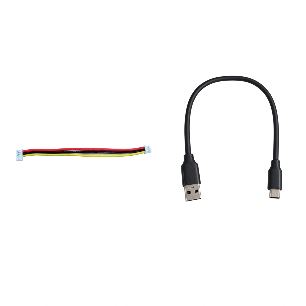
AeroMini Type-C + CVBS is a separate board: its actual board photograph shows the UVC socket and RXD, TXD, CVBS, GND and VCC labels, but no pin numbering, supply voltage or serial-direction definition. The Type-C kit cable photograph shows a three-wire harness and a USB-A to USB-C data cable; it does not establish how that harness mates to the board’s five-contact connector. Confirm the matched board and cable wiring guide before connecting power or serial signals.
SuperMini core interface: use Figure 3.1 and the complete 30-pin table in the SuperMini manual (PDF pages 6–7) for the factory core without an expansion board. These definitions are separate from AeroMini wiring and from the optional SuperMini expansion-board connectors.
Infrared camera module mechanical fit: check the configured assembly envelope
Small modules still create mechanical problems if the lens, cable, host PCB, or mounting direction is not planned. AeroMini’s published dimensions are 21 × 21 × 28 mm and weight is <20 g, excluding lens and flange. SuperMini’s published 13 × 13 × 13.4 mm and <3.5 g exclude lens, flange and user expansion board. These are different measurement scopes, not complete payload envelopes. For drone payloads, request the configured assembly drawing and compare it with the gimbal or fixed-mount envelope. For OEM devices, check PCB stack height, enclosure wall thickness, thermal path and connector service space. Use the linked SuperMini bare-core drawing within its stated scope, then request the selected assembly drawing before machining.
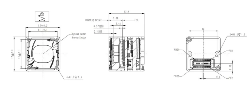
SuperMini bare-core mechanical reference: see Product Manual V1.0.0, Figure 4.1 (PDF page 13) for the official dimensioned drawing of the core without a lens or expansion board. Confirm the complete configured assembly before machining.
AeroMini assembly drawing: the current AeroMini datasheet provides interface-board layout and connector references, but no dimensioned assembly drawing. Request the drawing for the selected AeroMini lens, flange and interface-board assembly, including cable clearance. The linked SuperMini drawing does not apply to AeroMini.
5 common infrared camera module buying mistakes
- Comparing only resolution. A 640 × 512 module still needs the right lens/FOV, sensitivity, interface, power, and software workflow.
- Ignoring host interface early. USB video and the selected UART / RS232 / RS422 control path require board-specific planning; a connector name does not establish plug-and-play compatibility.
- Buying a cheap module without documentation. Low-cost boards can be useful for learning, but production projects need stable specs and supplier support.
- Skipping mechanical envelope checks. A compact module can still fail if the connector, lens, cable, or heat path is not planned.
- Sending a vague RFQ. “Need thermal camera price” usually creates slow matching. A real RFQ includes application, distance, lens/FOV, host, interface, dimensions, quantity, and market.
RFQ checklist: what to send CAMCUDA
- Application: drone inspection, outdoor observation, OEM machine vision, handheld device, robotics, or industrial equipment.
- Target distance, scene type, and whether the product needs detection, recognition, or inspection reporting.
- Resolution expectation and why 640 × 512 is being considered.
- Lens/FOV requirement or available optical envelope.
- Host processor, operating system, interface preference, and control path.
- Power budget, voltage rail, and battery or enclosure constraints.
- Mechanical space, weight limit, mounting direction, and cable constraints.
- Quantity range, destination market, compliance context, and timeline.
Need help matching the module to a real project?
Start with the AeroMini 640 product page, compare SuperMini 640 / 640T and Thermal Imaging Cores, review Drone Thermal Camera Application, or send your requirement sheet through CAMCUDA Contact / RFQ.
FAQ: buyer questions from drone and thermal communities
Is a 640 × 512 infrared camera module necessary for drone inspection?
Not always. For simple detection, a lower-resolution module may be enough. For solar, electrical, roof, or industrial inspection where the operator needs more detail, 640 × 512 is a stronger starting point. Reddit drone discussions around thermal inspection often mention 640 × 512 as a serious inspection class, but the final choice still depends on altitude, lens/FOV, reporting needs, and budget.
Can this module be used for solar farm inspection?
AeroMini can be evaluated for this workflow with 640 × 512 imaging, ≤30 mK NETD at 25°C, F/1.0 and 60 Hz default / 30 Hz factory-option imaging. Define flight height, panel size, lens/FOV, weather conditions and required report detail. For calibrated temperature readings, evaluate the separate 25 Hz AeroMini radiometric version or 30 Hz SuperMini 640T and confirm temperature-data output and thermographic conditions; imaging-only versions do not measure temperature.
Why do Reddit users talk so much about pricing for thermal solar inspection?
Because the camera is only one part of the job. Solar inspection pricing depends on site size, flight plan, irradiance/weather window, reporting depth, pilot certification, data processing, and whether the deliverable is anomaly detection or an engineering-grade report.
Is USB enough for real-time thermal video?
USB can be a practical video path when the selected AeroMini interface kit or SuperMini expansion board provides it. Real-time performance depends on host hardware, driver support, cable design, software pipeline and the selected output configuration. Confirm whether the workflow needs display video, image processing or a separately supported temperature-data path.
How should an OEM buyer plan USB video and serial control?
Plan image/video output and command/control separately. AeroMini offers UART, RS232 or RS422 depending on the board; SuperMini uses 1.8 V UART. Specify the selected board, host electrical levels, protocol and video receiver in the RFQ instead of assuming every connector or interface is available together.
How should I compare cheap infrared camera modules with this product?
Do not compare only price. Compare resolution, NETD, frame rate, pixel pitch, digital video path, control interface, power consumption, mechanical drawing, environmental values, image processing support, documentation, and supplier support.
Is AeroMini 640 a finished drone camera?
No. It is a compact uncooled LWIR thermal imaging module/core path for integration. A finished drone camera would also include enclosure, gimbal or mount, lens package, payload electronics, software, and aircraft integration.
What information should I send to CAMCUDA before requesting a quote?
Send application, host platform, interface preference, viewing distance, lens/FOV requirement, power limits, enclosure or payload constraints, expected quantity, destination market, and any required drawings or compliance context.
Can the module work outdoors?
AeroMini lists −40°C to +80°C operation; SuperMini imaging lists −40°C to +70°C. Both list 5–95% non-condensing humidity. Thermographic operating conditions must be confirmed separately. These are module limits, not an enclosure IP rating: outdoor success still depends on enclosure sealing, lens/window material, vibration isolation, condensation control and installation environment.
What is the fastest way to reduce integration risk?
Build a one-page infrared camera module requirement sheet before price negotiation: application, target distance, host processor, video/control interface, lens/FOV, mechanical envelope, power budget, environmental requirement, quantity, and timeline.