OEM Camera Sourcing Guide: How to Source Embedded & Thermal Camera Modules
OEM Camera Sourcing Guide: How to Source Embedded & Thermal Camera Modules
Engineering vision systems for autonomous unmanned aerial vehicles (UAVs), tactical robotics, perimeter security gimbals, and high-speed industrial inspection platforms demands a brutal hardware selection process. Sourcing embedded electro-optical (EO) and long-wave infrared (LWIR) camera modules is miles apart from grabbing an off-the-shelf USB web sensor or a standard action camera. Lead systems architects, embedded Linux engineers, and hardware procurement leads have to balance sensor physics, high-speed serialization interfaces, edge neural compute envelopes, and long-term bill-of-materials (BOM) availability.
Here’s the deal: a poorly planned camera sourcing pipeline creates fatal bottlenecks on the bench and in the field. You end up with severe optical disparity between visible and thermal channels, unmanageable kernel driver latency that blows past your closed-loop flight-controller update window, brutal thermal throttling on SWaP-constrained (Size, Weight, Power, and Cost) airframes, and sudden component obsolescence that kills production runs. This industrial guide gives you an end-to-end technical roadmap for sourcing embedded single- and dual-spectrum camera modules, breaking down raw sensor architectures, protocol trade-offs, edge AI tracking acceleration, production module benchmarks, and supply chain qualification standards.
Table of Contents
- 👉 1. Core Engineering Parameters: Sensor Physics & Spectral Matching
- 👉 2. Interface Protocols & Bus Architectures: MIPI vs. USB vs. Parallel DVP
- 👉 3. Edge AI Co-Processing & Real-Time Tracking Compute
- 👉 4. OEM Product Benchmark: Dual-Spectrum AI Tracking Modules
- 👉 5. Procurement Framework: Supply Chain Integrity & Frozen BOMs
- 👉 6. Frequently Asked Questions
1. Core Engineering Parameters: Sensor Physics & Spectral Matching
When you sit down to select optical and thermal hardware for embedded vision payloads, you have to look past marketing spec sheets. Forget headline megapixel numbers. What really matters in the field comes down to raw quantum efficiency, dynamic range, thermal sensitivity, and optical spatial registration.
Visible CMOS Sensors: Quantum Efficiency and Dynamic Range
Visible-spectrum electro-optical (EO) imagers use silicon CMOS photodiode arrays sensitive to wavelengths between 380 nm and 750 nm. In field robotics and airborne reconnaissance, lighting conditions swing wildly—from direct high-noon solar reflection exceeding 100,000 lux down to pitch-black starlight environments below 0.001 lux. Pulling clean frames in low light requires large optical formats (like 1/1.8-inch sensors) matched with Back-Illuminated (BSI) pixel architectures that route the metal wiring behind the photodiode layer to maximize photon capture.
Look for sensor specs that deliver a true hardware wide dynamic range (WDR) of at least 100 dB to 120 dB via multi-exposure HDR or dual-gain readout circuits (such as DCG architectures). This keeps the sky from blowing out into pure white while retaining critical target details in deep shadows. You also need to watch rolling shutter skew. When your drone or robotic platform executes high-speed yaw maneuvers or tracks fast-moving ground vehicles, rolling shutter artifacts will turn straight vertical lines into slanted jello. For high-speed platforms, opt for global shutter sensors or high-frame-rate rolling shutter imagers pushing 60 Hz to 120 Hz with sub-10 ms readout times.
Uncooled LWIR Thermal Detectors: VOx vs. a-Si Physics
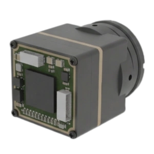
Thermal imaging operates within the Long-Wave Infrared (LWIR) band between 8 µm and 14 µm, detecting photon emissions governed by Planck’s law of blackbody radiation as defined in the ISO 10878 Infrared Thermography Vocabulary. For SWaP-constrained embedded vision systems, cooled cryo-detectors are out of the question due to power, size, and service-life limits. That leaves uncooled microbolometers.
| Parameter | Vanadium Oxide (VOx) Microbolometer | Amorphous Silicon (a-Si) Microbolometer |
|---|---|---|
| Temperature Coefficient of Resistance (TCR) | Higher (~2% to 3% / K), yielding superior signal-to-noise ratios. | Lower (~1.5% to 2% / K), requiring higher gain amplification. |
| Thermal Sensitivity (NETD) | Typical ≤ 30–40 mK, providing crisp target edge definition. | Typical ≥ 50 mK, showing higher thermal background noise. |
| Pixel Pitch Scalability | Mature at 12 µm pitch, enabling smaller optical Germanium lenses. | Often 17 µm; 12 µm transitions present higher 1/f noise profiles. |
| Non-Uniformity Correction (NUC) | Lower thermal drift; longer operational cycles between shutter calibrations. | Higher susceptibility to ambient drift; requires frequent calibration. |
In the shop, we consistently recommend uncooled VOx cores running a 12 µm pixel pitch and 640 x 512 resolution for any mission-critical edge AI payload. If you are designing a low-cost thermal tripwire or basic presence sensor, smaller formats like the TC160-NF 160×120 LWIR Thermal Imaging Module can save serious money. But if you need an AI tracker to cleanly segment a human or vehicle at 300 to 800 meters, 640 x 512 is your real-world baseline.
Optical Parity & Dual-Spectrum Spatial Registration
When you build a dual-spectrum gimbal, aligning the field of view (FOV) across both channels is critical. Dual-spectrum fusion and Picture-in-Picture (PIP) pipelines work by overlaying thermal energy maps directly on top of high-frequency visible edge maps. If your visible camera runs an ultrawide 109° horizontal FOV and your thermal core is locked to a narrow 47.7° FOV, your host processor will waste massive compute power on homography warping, digital cropping, and affine transformations just to line up pixels. Align your focal lengths and optical centers early during hardware specification to keep image alignment workloads from choking your NPU.
2. Interface Protocols & Bus Architectures: MIPI vs. USB vs. Parallel DVP
Your hardware bus interface sets the ceiling for latency, processing overhead, PCB routing complexity, and signal integrity. Sourcing the wrong electrical interface will stall an embedded system before the first prototype leaves the lab.
| Interface Protocol | Raw Throughput | Host Processing Latency | Max Trace Length | Integration Complexity |
|---|---|---|---|---|
| MIPI CSI-2 (D-PHY) | Up to 2.5 Gbps per lane (10 Gbps 4-lane) | < 5 ms (Direct DMA to ISP/NPU) | < 15–20 cm (Direct FPC) | High (Requires Linux V4L2 drivers & Device Tree configuration) |
| USB 3.0 / USB3.1 (UVC) | 5 Gbps to 10 Gbps | 15 ms – 35 ms (USB Host Stack Buffer) | Up to 3–5 meters | Low (Standard UVC driver stack plug-and-play) |
| Parallel DVP | < 1.5 Gbps (Limited by clock skew) | < 8 ms | < 10 cm | Medium (High pin count, EMI radiation challenges) |
| GMSL2 / FPD-Link III | Up to 6 Gbps over coax/STP | < 6 ms (SerDes bridge overhead) | Up to 15 meters | High (Requires dedicated SerDes ICs and coaxial routing) |
For a complete breakdown of raw pinouts, differential pairs, and signal levels, check out our deep-dive engineering guide on thermal camera module interfaces (USB, MIPI, CVBS, DVP).
MIPI CSI-2 Implementations
MIPI CSI-2 remains the gold standard for high-performance edge vision. Direct memory access (DMA) pumps uncompressed raw pixel streams straight into system RAM and hardware Image Signal Processors (ISPs), completely avoiding the OS networking or USB stacks. This keeps end-to-end capture latency well under 5 ms—vital for closed-loop flight maneuvers. That said, routing high-speed MIPI differential pairs requires disciplined high-frequency RF layout practices: strict differential impedance matching at 100 ohms, length-matched traces within ±0.15 mm, solid ground reference planes, and isolated power rails to prevent switching regulator ripple from degrading sensor performance.
USB 3.0 UVC Architectures
USB Video Class (UVC) modules shine during proof-of-concept bench prototyping. You plug into Linux, Windows, or Android hosts and pull clean video streams without touching kernel device trees or debugging custom V4L2 driver patches. But in real-time tactical systems, USB host controller scheduling and driver buffering introduce jitter and frame latency spikes between 15 ms and 40 ms. If your target is moving at high speed, that latency lag will cause PID tracking loops to oscillate and drop lock.
3. Edge AI Co-Processing & Real-Time Tracking Compute
Tactical robotics and autonomous systems must process data at the tactical edge. Relying on remote RF video links to a ground control station (GCS) introduces transmission latency, exposes platforms to jamming, and fails in GPS-denied environments. Leading hardware builds in the NVIDIA Embedded Computing ecosystem and specialized tracking boards integrate dedicated Neural Processing Units (NPUs) directly into the camera carrier assembly.
Heterogeneous NPU Architectures
Don’t get tricked by raw TOPS figures alone. An NPU with 6 TOPS running an unoptimized INT8 model on a choked memory bus will perform worse than an efficient 4 TOPS engine backed by dedicated SRAM and optimized Multiply-Accumulate (MAC) pipelines. A balanced edge platform couples high-performance ARM application cores (such as dual Cortex-A76 running at 2.4 GHz alongside Cortex-A55 efficiency cores) with a hardware NPU.
This heterogeneous architecture lets the CPU manage flight telemetry, target classification states, and H.264/H.265 compression, while the NPU runs YOLOv8-nano or MobileNet-SSD detection models at 50 Hz to 120 Hz. Processing high-frame-rate video on-chip allows bounding box coordinates to be extracted before downscaling or transmitting video.
Tracking Logic and Telemetry Integration
A production-ready target tracking engine handles multiple operational steps:
- ⚙️ Target Bounding & Acquisition: Neural networks detect target classes (dismounted personnel, civilian vehicles, armored assets) down to a tiny 10 x 10 pixel patch.
- ⚙️ Multi-Object Tracking (MOT): DeepSORT and ByteTrack algorithms assign unique tracking IDs, maintaining continuous lock on up to 120 targets across the frame.
- ⚙️ Lost-Target Recall: Advanced Kalman filter state estimators predict target trajectories through dense foliage, overpass bridges, or temporary structural occlusions.
- ⚙️ Direct Autopilot Protocol Support: The board feeds angular error offsets directly to open-source flight stacks (ArduPilot, Betaflight, PX4) via the CRSF (Crossfire) serial protocol, keeping pursuit loops tight without requiring an external companion computer.
4. OEM Product Benchmark: Dual-Spectrum AI Tracking Modules
To see these engineering principles in production hardware, let’s examine two dual-spectrum tracking modules deployed across commercial and defense applications.
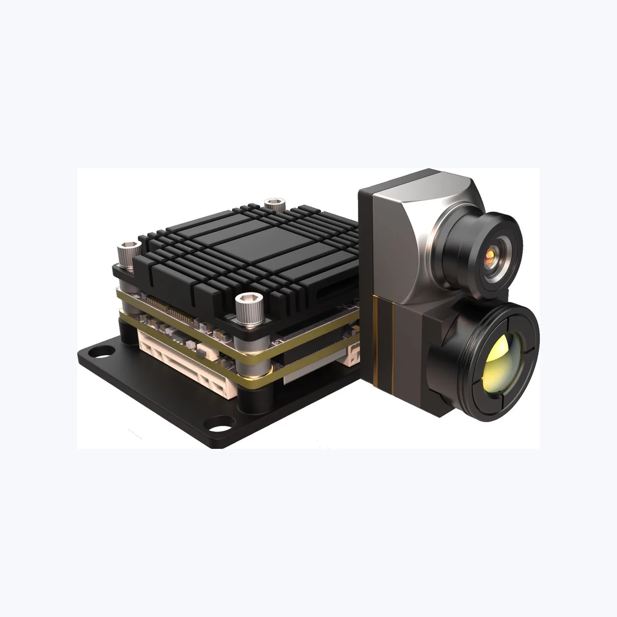
TC01-DUAL: 4 TOPS Dual-Spectrum UAV AI Tracking Module
The TC01-DUAL pairs a wide-angle visible camera with a 640 x 512 uncooled LWIR thermal core, supported by a 4 TOPS edge AI compute carrier board. It is built specifically for sub-250g tactical drones, robotic perimeter nodes, and light reconnaissance systems that require continuous multi-spectrum object tracking in a compact footprint.
| TC01-DUAL Technical Specifications | |
|---|---|
| Edge AI Compute | 4 TOPS Edge Processing Engine |
| Visible (EO) Camera | 1/1.8-inch CMOS, 2160 x 1440 @ 60 Hz, 4.37 mm lens (FOV: D 131.6° / H 109° / V 57.5°), 0.001 lux min illumination |
| Thermal (LWIR) Camera | 640 x 512 @ 50 Hz, 8–14 µm spectral range, 12 µm pixel pitch, 9.1 mm lens (FOV: D 61.8° / H 47.7° / V 38.2°) |
| Tracking & Latency | Vehicle: 800 m / Person: 300 m range; ~30 ms latency reference; up to 60 identified targets; speeds up to 140 km/h |
| Integration & Mechanical | CRSF protocol, BetaFlight & ArduPilot support; 9–16 V DC regulated input; 38 x 38 x 24.5 mm board (25.5 x 25.5 mm mount) |
View Product Details & Pricing ➔
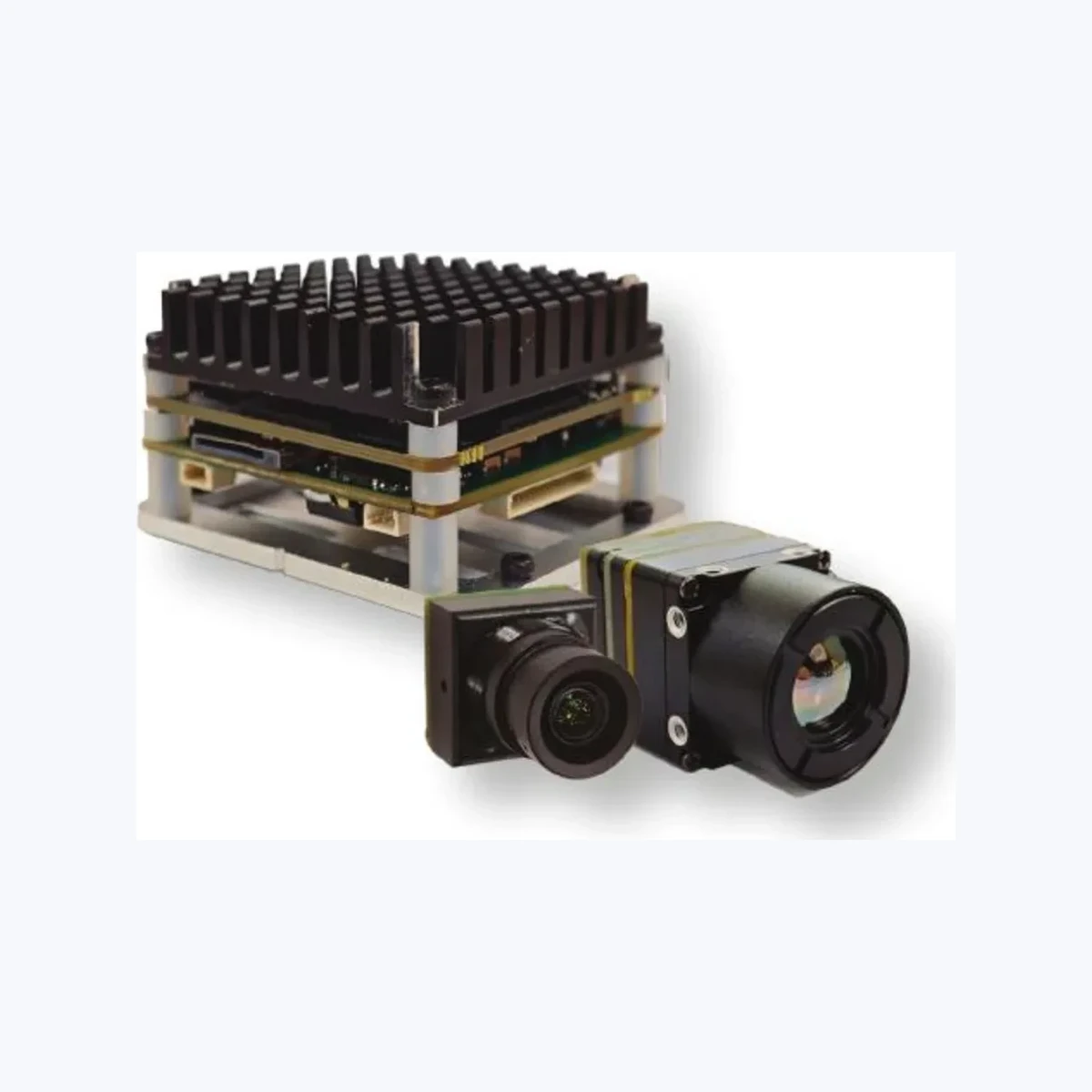
TM02-SOLO T: 6 TOPS High-Speed Dual-Spectrum Tracking Module
The TM02-SOLO T is designed for demanding, high-velocity intercept and tracking missions. Powered by a dual-core Cortex-A76 and Cortex-A55 architecture alongside a 6 TOPS NPU, it processes a 120 Hz EO visible stream in parallel with an uncooled VOx 640 x 512 thermal channel at 50 Hz, keeping tracking latency down to an impressive ~8 ms.
| TM02-SOLO T Technical Specifications | |
|---|---|
| Edge AI Compute & CPU | 6 TOPS Edge AI; Arm Cortex-A76 @ 2.4 GHz + Cortex-A55 @ 1.8 GHz |
| Visible (EO) Camera | 1/1.8-inch CMOS, 1920 x 1080 @ 120 Hz, 8.45 mm lens (FOV: D 66.3° / H 57.1° / V 30.4°), 0.001 lux low-light sensitivity |
| Thermal (LWIR) Camera | 640 x 512 @ 50 Hz Uncooled VOx, 8–14 µm, 12 µm pixel pitch, 9.1 mm lens (FOV: D 61.8° / H 47.7° / V 38.2°) |
| Tracking & Dynamic Speeds | Vehicle: 400 m / Person: 170 m range; ~8 ms processing latency reference; up to 120 target tracks; speeds up to 450 km/h |
| Tracking Modes & Control | Reticle locking, close-to-lock, route pre-map, lost-target recall, PIP; CRSF protocol for BetaFlight / ArduPilot |
| Physical & Electrical | Regulated 9–16 V DC; Board: 45 x 45 x 26 mm (Mount: 42.5 x 42.5 mm); MIPI connection reference |
View Product Details & Pricing ➔
Direct Side-by-Side Comparison
| Feature | TC01-DUAL (4 TOPS) | TM02-SOLO T (6 TOPS) |
|---|---|---|
| Compute Architecture | 4 TOPS Dedicated NPU Engine | 6 TOPS NPU + Cortex-A76/A55 Heterogeneous CPU |
| EO Video Stream | 2160 x 1440 @ 60 Hz (Wide FOV: 109° H) | 1920 x 1080 @ 120 Hz (Narrow FOV: 57.1° H) |
| Thermal Sensor | 640 x 512 @ 50 Hz LWIR (12 µm) | 640 x 512 @ 50 Hz Uncooled VOx (12 µm) |
| Target Speed Capability | Up to 140 km/h | Up to 450 km/h |
| Processing Latency | ~30 ms reference | ~8 ms reference |
| Active Tracks Capacity | Up to 60 Targets | Up to 120 Tracks (Advanced Re-ID) |
| Board Size & Mounting | 38 x 38 x 24.5 mm (25.5 mm mount) | 45 x 45 x 26 mm (42.5 mm mount) |
5. Procurement Framework: Supply Chain Integrity & Frozen BOMs
Moving from a benchtop prototype to high-volume manufacturing is where hardware programs run into supply chain landmines. An experienced engineering procurement strategy sets hard commercial and technical boundaries before issuing purchase orders.
Frozen Bill of Materials (BOM) & PCN Agreements
Unannounced component swaps are the top reason embedded vision systems fail in field deployment. A vendor silently swapping a passive decoupling capacitor, revising an EEPROM, or migrating to a new silicon stepping can wreck Linux kernel driver timing, compromise thermal dissipation, or introduce EMI emissions that blow past compliance limits.
In all OEM procurement agreements, mandate strict Frozen BOM clauses. Your contracts must require:
- ✅ Mandatory PCN Alerts: Written Product Change Notifications (PCNs) delivered at least 90 to 180 days prior to any component substitution.
- ✅ Last-Time-Buy (LTB) Guarantees: Guaranteed minimum notice and buffer stock options before parts go End-of-Life (EOL).
- ✅ Lifecycle Commitment: Guaranteed production availability for 3 to 5 years minimum, preventing costly PCB redesigns halfway through a project lifecycle.
Environmental Stress Screening (ESS) & Power Integrity
Hardware destined for drones, industrial robotics, and outdoor vehicles takes a beating. Make sure your supplier validates the following critical engineering points:
- ⚙️ TVS Protection & Wide DC Input: Ensure carrier boards integrate high-capacity Transient Voltage Suppression (TVS) diodes and internal switching regulation supporting 9–16 V DC inputs, guarding against motor back-EMF voltage spikes.
- ⚙️ Vibration and Shock Profiling: Verify solder joint reliability, surface-mount Hirose/I-PEX connector retention, and optical barrel thread locking against MIL-STD-810H vibration and mechanical drop profiles.
- ⚙️ Direct Conduction Cooling: Confirm the module architecture includes thermal interface material (TIM) paths that sink heat directly into external gimbal walls or aluminum chassis, keeping sensor calibration stable and stopping NPU throttling.
- ⚙️ Regulatory Standards: Confirm supplier compliance with international environmental and electrical safety directives, as detailed in our EU compliance and regulatory framework (covering CE, RoHS, REACH, and EMC certifications).
6. Frequently Asked Questions
How do embedded hardware teams source camera modules directly from manufacturers instead of retail brokers?
What key technical specifications must procurement managers verify during thermal and dual-spectrum camera sourcing?
- Thermal Core: Confirm microbolometer type (VOx is standard), pixel pitch (12 µm), spectral band (8–14 µm LWIR), and thermal sensitivity (NETD ≤ 40–50 mK).
- Visible Sensor: Verify low-light performance (0.001 lux), true hardware dynamic range (≥ 100 dB WDR), and frame rates (60–120 Hz) to eliminate high-speed pan blur.
- Optics & Parity: Check that horizontal and vertical FOVs across both channels match your target DRI (Detection, Recognition, Identification) distance requirements.
- Compute Engine: Confirm real edge NPU capability (4 to 6 TOPS), full-pipeline latency (< 30 ms), supported neural tracking architectures, and thermal limits under continuous inferencing.
How do we mitigate supply chain and firmware compatibility risks when buying bulk camera modules?
📚 References & Further Reading
- Industry Standard: ISO 10878 Infrared Thermography Vocabulary
- Compute Platform: NVIDIA Embedded Computing Architecture
- Related Guide: Thermal Camera Module Interfaces (USB, MIPI, CVBS, DVP)
- Regulatory Compliance: CamCuda EU Compliance & Standards Overview
- Compact LWIR Sourcing: TC160-NF 160×120 LWIR Thermal Imaging Module