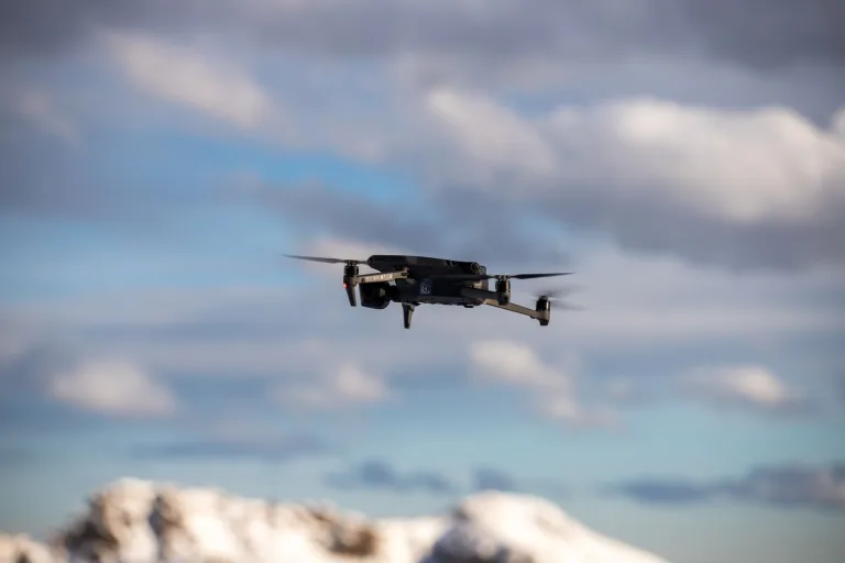
Infrared Drones & Thermal Payloads: OEM Integration & SWaP Buying Guide
Infrared Drones & Thermal Payloads: OEM Integration & SWaP Buying Guide
In modern industrial inspection, public safety operations, and defense aerospace programs, aerial thermal imaging has moved past the experimental gadget stage. It is now a mandatory requirement on the flight line. Bolting long-wave infrared (LWIR) sensors onto unmanned aerial systems (UAS)—what the industry broadly classifies as infrared drones—gives operators uncompromised situational awareness through pitch-black nights, thick smoke, industrial smog, and high-contrast thermal environments. Whether you are running aerial utility grid inspections, hunting micro-cracks across a massive photovoltaic farm, maintaining tactical perimeter security, or coordinating rapid search-and-rescue (SAR) sweeps, thermal drones convert raw heat radiation into clean spatial telemetry and calibrated radiometric datasets.
Here’s the deal: getting a thermal payload onto a multi-rotor or fixed-wing airframe is an exercise in ruthless engineering compromise. Systems architects and integration engineers spend their days balancing microbolometer physics, raw radiometric resolution, optical focal lengths, and frame rate stability against unforgiving Size, Weight, Power, and Cost (SWaP-C) limits. Turnkey commercial infrared drones are fine for off-the-shelf basic tasks, but they inevitably box enterprise teams into closed proprietary software ecosystems, locked data formats, and rigid mechanical mounts that ruin modularity.
This guide cuts through the marketing fluff. We break down the core engineering principles of aerial thermal sensing, examine low-level hardware buses and edge-AI compute stacks, evaluate optical physics using Johnson’s Criteria, and review real-world hardware specifications for modular uncooled thermal cores and tactical observation gear.
Table of Contents
- 👉 1. Uncooled LWIR Thermal Imaging Fundamentals for Aerial Systems
- 👉 2. SWaP-C Optimization in Aerial Gimbal Enclosures
- 👉 3. Digital Interfacing, Processing Pipelines & Edge-AI Compute
- 👉 4. Lens Selection, Thermal Optics Physics & Johnson’s Criteria
- 👉 5. OEM Thermal Cores & Observation Instruments Specification Matrix
- 👉 6. System Integration Workflows, Compliance & Procurement Guidelines
- 👉 7. Deep-Dive Engineering FAQ: Thermal UAV Payloads
1. Uncooled LWIR Thermal Imaging Fundamentals for Aerial Systems
Thermal infrared imaging operates across the invisible electromagnetic spectrum where detectors measure emitted heat energy rather than reflected visible light photons. For airborne drone payloads, we work predominantly inside the Long-Wave Infrared (LWIR) atmospheric transmission window, which covers nominal wavelengths from 8 µm to 14 µm. If you want to design a rock-solid payload, you have to understand detector physics under dynamic flight regimes.

Microbolometer Architecture: VOx vs. a-Si in Dynamic Flight Regimes
Modern aerial thermal payloads rely on uncooled Focal Plane Array (FPA) microbolometers. Unlike heavy, power-hungry cryogenically cooled Mid-Wave Infrared (MWIR) or Short-Wave Infrared (SWIR) sensors, uncooled microbolometers run at ambient temperatures. This strips out the bulky Stirling cycle cooling engines and slashes the payload SWaP footprint. Inside uncooled FPAs, you will run into two competing detector materials: Vanadium Oxide (VOx) and Amorphous Silicon (a-Si).
In aerospace and tactical builds, Vanadium Oxide (VOx) is the undisputed workhorse. VOx microbolometers deliver a significantly higher Temperature Coefficient of Resistance (TCR) than a-Si—typically around -2% to -3% per Kelvin. That high TCR means the sensor registers tiny resistance shifts when incoming infrared photons hit the microbolometer membrane. On top of that, VOx has a lower 1/f noise floor and a faster thermal time constant (typically 8–12 ms). That speed is vital: when an airframe pulls high-speed yaw maneuvers or tracks terrain at 15 m/s, a slow sensor produces spatial ghosting and image smear. Hardware built by engineering teams like Camcuda leverages uncooled VOx matrices with tight 12 µm pixel pitches to extract maximum spatial resolution out of ultra-compact envelopes.
Thermal Sensitivity: Understanding NETD Under Aerodynamic Cooling
Noise Equivalent Temperature Difference (NETD) is the defining metric for sensor sensitivity. Stated in millikelvins (mK), NETD marks the temperature variation that yields a signal-to-noise ratio (SNR) of exactly one. When running airborne surveys, a lower NETD value translates straight into crisp thermal contrast across low-gradient scenes.
Look at the numbers: an NETD rating of ≤20 mK (@25°C, F/1.0) completely outclasses legacy ≤50 mK detectors. Consider high-altitude utility audits. Subsurface delamination on a wind turbine blade or early-stage cell degradation in a solar string often produces a localized temperature delta of less than 0.5°C against surrounding structures. When your drone flies at speed, prop-wash and ambient air velocity create convective cooling that strips surface heat away, dampening that delta even further. A sensor rated at ≤20 mK slices through background thermal noise, ensuring you spot micro-anomalies in freezing, windy, or heavily overcast flight windows.
Frame Rates (25 Hz vs. 50 Hz) and Motion Blur Mitigation During High-Speed Transects
Flight speed sets your minimum frame rate ceiling. Standard commercial thermal modules are frequently throttled to 9 Hz to sidestep historical export controls. In the shop, we tell clients outright: 9 Hz is useless for dynamic airborne tracking. At a standard survey speed of 12 m/s, a 9 Hz sensor captures one frame every 1.33 meters of lateral flight. That gap introduces rolling-shutter tearing, spatial smear, and ruins automated edge-detection passes.
For standard hover inspections and slow grid patterns, 25 Hz or 30 Hz is your baseline. But for fixed-wing airframes, high-speed pipeline transects, and fast tactical tracking, a native 50 Hz refresh rate is mandatory. Running at 50 Hz cuts the inter-frame integration window, keeps edges razor-sharp across rapid linear passes, and supplies a reliable temporal feed for visual-inertial odometry (VIO) and autonomous obstacle-avoidance computers.
2. SWaP-C Optimization in Aerial Gimbal Enclosures
Every single gram of payload weight and milliwatt of power draw extracts a direct tax on drone flight dynamics. Systems engineers must treat Size, Weight, Power, and Cost (SWaP-C) as a zero-sum game.
Weight-to-Loiter Dynamics: Impact of Core and Lens Mass on Flight Endurance
Multi-rotor loiter time is governed by momentum theory and rotor disc loading. The hover power draw of an airframe scales non-linearly with all-up-weight (AUW). On a typical enterprise quad or hexacopter, hanging an extra 100 grams of gimbal mass cuts battery flight time by 2 to 5 minutes depending on pack chemistry and payload configuration.
Payload mass also punishes the 3-axis brushless gimbal. Brushless gimbal motors require continuous holding torque to stabilize heavy optical stacks. When you mount a heavy Germanium telephoto lens (like a 50 mm F/1.0 assembly weighing over 200 g) far out on the pitch axis, the payload’s rotational moment of inertia spikes. That forces you to use larger motor stators, draws higher peak currents, and risks inducing mechanical resonance during aggressive wind buffeting.
Thermal Throttling: Heat Dissipation Mechanisms in Sealed Gimbals
Unlike visible CMOS sensors, uncooled microbolometers generate their own baseline heat from internal Readout Integrated Circuits (ROIC), high-speed ADCs, and onboard FPGAs running real-time Non-Uniformity Correction (NUC). Drone thermal payloads are usually housed in IP54 to IP67 sealed pods to lock out moisture and dust during field operations.
Sealing an enclosure eliminates convective air cooling for internal chips. Without dedicated thermal conduction paths, the interior of a gimbal housing can easily climb past 70°C, causing microbolometer thermal drift. As the sensor housing heats up unevenly, the FPA is forced to trigger frequent mechanical shutter recalibrations (NUC cycles), freezing the video stream for 500 to 1000 milliseconds right when you need it most. To solve this without fans, mechanical engineers design direct conduction routes with high-performance thermal gap pads (>6 W/m-K) that dump FPGA core heat straight into the aluminum gimbal shell, using the aircraft’s rotor downwash for passive convective cooling.
Power Consumption Constraints: Ultra-Low Power vs. Standard Payloads
Power budgets on embedded drone busses are split between flight controllers, propulsion, telemetry links, edge computers, and auxiliary sensors. Market reporting from Commercial UAV News confirms that sub-watt payload architectures are driving the next generation of long-endurance autonomous platforms.
Standard industrial thermal cores draw between 1.5 W and 3.5 W during steady operation. On heavy-lift rigs that is manageable, but on tactical micro-drones or autonomous reconnaissance birds, that draw drains battery reserves fast. Ultra-low-power modules running around 76–80 mW operate cleanly on standard 3.3 V rails. These micro-cores can tap straight into host MCU buses, enabling continuous 360-degree thermal collision avoidance and localized proximity sensing without stealing power from the primary motors.
3. Digital Interfacing, Processing Pipelines & Edge-AI Compute
Plugging a thermal core into an autonomous flight architecture requires picking the right physical data bus, video encoding pipeline, and onboard computing stack.
Embedded Communication Protocols: SPI, MIPI-CSI2, USB, and Parallel FPC
Your hardware interface choice decides your transmission bandwidth, routing complexity, and processor compatibility:
- ⚙️ Serial Peripheral Interface (SPI): The go-to standard for micro-resolution cores (e.g., 160×120 pixels). SPI runs over a lean 4-wire synchronous bus (SCLK, MOSI, MISO, CS), making it easy to route through compact gimbal slip rings. A high-speed SPI bus running at 20–40 MHz effortlessly delivers 14-bit raw radiometric frames at 25 FPS into lightweight microcontrollers or compact embedded Linux boards.
- ⚙️ MIPI-CSI2 (Mobile Industry Processor Interface): The industry benchmark for high-resolution thermal video (384×288 and 640×512). MIPI-CSI2 utilizes differential signaling over dedicated clock and data lanes, streaming uncompressed thermal frames directly into the host System-on-Chip (SoC) Image Signal Processor (ISP) with zero CPU overhead and sub-millisecond pipeline latency.
- ⚙️ Parallel Video (DVP / CMOS FPC): Legacy 8-bit to 16-bit parallel buses using ribbon cables. While straightforward on custom test benches, parallel routing picks up severe electromagnetic interference (EMI) from high-frequency drone ESCs and requires wide traces that make gimbal slip-ring pass-throughs a nightmare.
- ⚙️ USB 2.0 / USB 3.0 (UVC Standard): Excellent for rapid prototyping, secondary payload pods, and modular setups. The standard USB Video Class (UVC) layer lets thermal modules push pre-processed video or raw data directly into companion single-board computers (SBCs) without writing custom kernel drivers.
Radiometric vs. Non-Radiometric Video Streams for Edge Processing
Here is an important distinction: you must know whether your processing pipeline needs radiometric data or basic video. A non-radiometric stream outputs standard 8-bit grayscale or colorized (White-Hot, Ironbow) video. Pixel values are mapped between 0 and 255 via internal Automatic Gain Control (AGC) curves. This is fine for a human pilot flying by eye, but it strips away all calibrated temperature data.
A radiometric data pipeline outputs raw 14-bit or 16-bit digital values per pixel. Each discrete value ties back mathematically to an absolute temperature point calculated against internal Planck calibration tables. If you are building automated inspection systems, you must preserve this 14-bit pipeline all the way to the companion computer. That raw depth allows edge scripts to run real-time delta-T calculations, trigger automated fire thresholds, and build accurate radiometric photogrammetry orthomosaics.
Real-Time Inference on Companion Computers (NVIDIA Jetson Architecture)
Modern autonomous infrared drones lean on onboard companion compute engines to run neural networks at the tactical edge. Hardware powered by the NVIDIA JetPack SDK (like the Jetson Orin Nano and Orin NX) delivers the tensor computing power needed for multi-spectral sensor fusion, automated target tracking, and object classification.
To run real-time inference at 50 FPS, engineers route raw frames over MIPI-CSI2 or USB straight into CUDA-mapped memory. A TensorRT-optimized convolutional neural network (such as YOLOv8 or custom thermal segmentation models) ingests the 14-bit radiometric or 8-bit thermal tensor. The system can isolate human heat signatures under dense canopies, spot overheating transformer bushings on power grids, and send real-time bounding box offsets over MAVLink/CAN buses to command autonomous camera tracking orbits.
4. Lens Selection, Thermal Optics Physics & Johnson’s Criteria
Thermal optical design is a completely different animal than visible-light imaging. Standard optical glass is 100% opaque to long-wave infrared radiation. Thermal systems demand exotic infrared materials paired with exact focal length calculations to hit mission spatial resolution requirements.
Germanium Optics vs. Chalcogenide Glass: Transmittance and Weight Profiles
Drone thermal lens assemblies rely on two core optical materials:
- ✅ Germanium (Ge): Single-crystal Germanium features an exceptionally high refractive index (n ≈ 4.0 in the 8–14 µm band) and top-tier transmission when paired with anti-reflective (AR) and Diamond-Like Carbon (DLC) hard coatings. Its high refractive index allows optical engineers to use shallower lens curvatures and minimize spherical aberrations with fewer elements. The catch? Germanium is heavy (5.32 g/cm³), costly, and prone to thermal de-focusing (thermal lensing) due to its high thermo-optic coefficient (dn/dT), requiring mechanical or optical athermalization across wide operational temperatures.
- ✅ Chalcogenide Glass: Chalcogenide compounds (amorphous glass using selenium, sulfur, and tellurium) provide a lightweight, cost-effective alternative. Because it can be precision-molded into complex aspheric and diffractive shapes, designers can build compact, low-element lens groups that drastically cut payload weight. While raw transmission is slightly below coated Germanium, Chalcogenide glass maintains outstanding athermal stability from -20°C up to +85°C.
Calculating Ground Sampling Distance (GSD) and Standoff Distances
Ground Sampling Distance (GSD) is the physical footprint on the ground covered by the center-to-center distance of two adjacent detector pixels. Calculating GSD is mandatory when setting your flight ceiling and selecting lenses for infrastructure inspection.
The standard formula for calculating thermal GSD is:
Where:
- ⚙️ p: Pixel Pitch of the microbolometer array (e.g., 12 µm = 0.012 mm).
- ⚙️ H: Flight Altitude Above Ground Level (AGL) in meters.
- ⚙️ f: Focal Length of the objective lens in millimeters.
Let’s run the math: take an infrared drone flying a 640×512@12 µm core with a 25 mm lens at 50 meters AGL:
Swap that out for a 50 mm telephoto lens on the same airframe, and your GSD tightens to 1.2 cm/pixel at the exact same 50-meter standoff distance. That extra resolving power allows you to inspect energized high-voltage disconnects without flying dangerously close to electro-magnetic interference envelopes.
Johnson’s Criteria in Practice: Detection, Recognition, and Identification (DRI)
Johnson’s Criteria gives engineers an empirical standard to calculate the real-world performance of an electro-optical thermal system against standardized targets (such as a 0.75 m human dimension or a 2.3 m vehicle profile):
- 🔍 Detection (1.5 cycles on target): The operator or edge-AI detects a heat anomaly or object in the field (occupying roughly 3 to 4 pixels across its critical dimension).
- 🔍 Recognition (6.0 cycles on target): The operator can classify the target category (differentiating a human from a quadruped animal or light vehicle; occupying roughly 12 to 16 pixels).
- 🔍 Identification (12.0 cycles on target): The operator makes a positive, detailed identification (verifying equipment carried by personnel or pinpointing a specific vehicle class; occupying 24 to 32 pixels).
Lens selection is always a direct trade-off between wide situational awareness and long-range DRI capabilities. Wide optics (such as 56° DFOV) are ideal for close-quarters obstacle avoidance and structural surface mapping. Narrow telephoto optics (like 50 mm lenses with <15° HFOV) are required for tactical standoff reconnaissance and high-voltage corridor patrols.
5. OEM Thermal Cores & Observation Instruments Specification Matrix
Depending on the deployment model, aerospace integrators must choose between embedding component-level uncooled LWIR sensor cores into custom drone gimbals or equipping ground support teams with ruggedized observation instruments for ground-truth anomaly verification and search coordination.
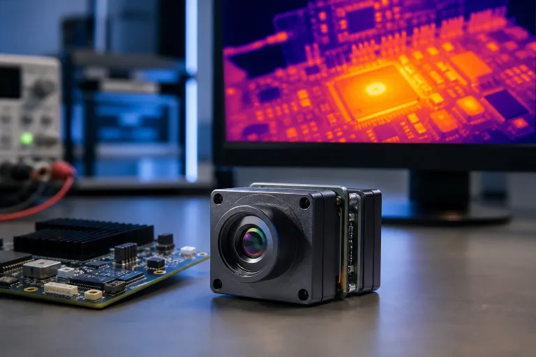
TC160-NF 160×120 Uncooled LWIR Thermal Imaging Module
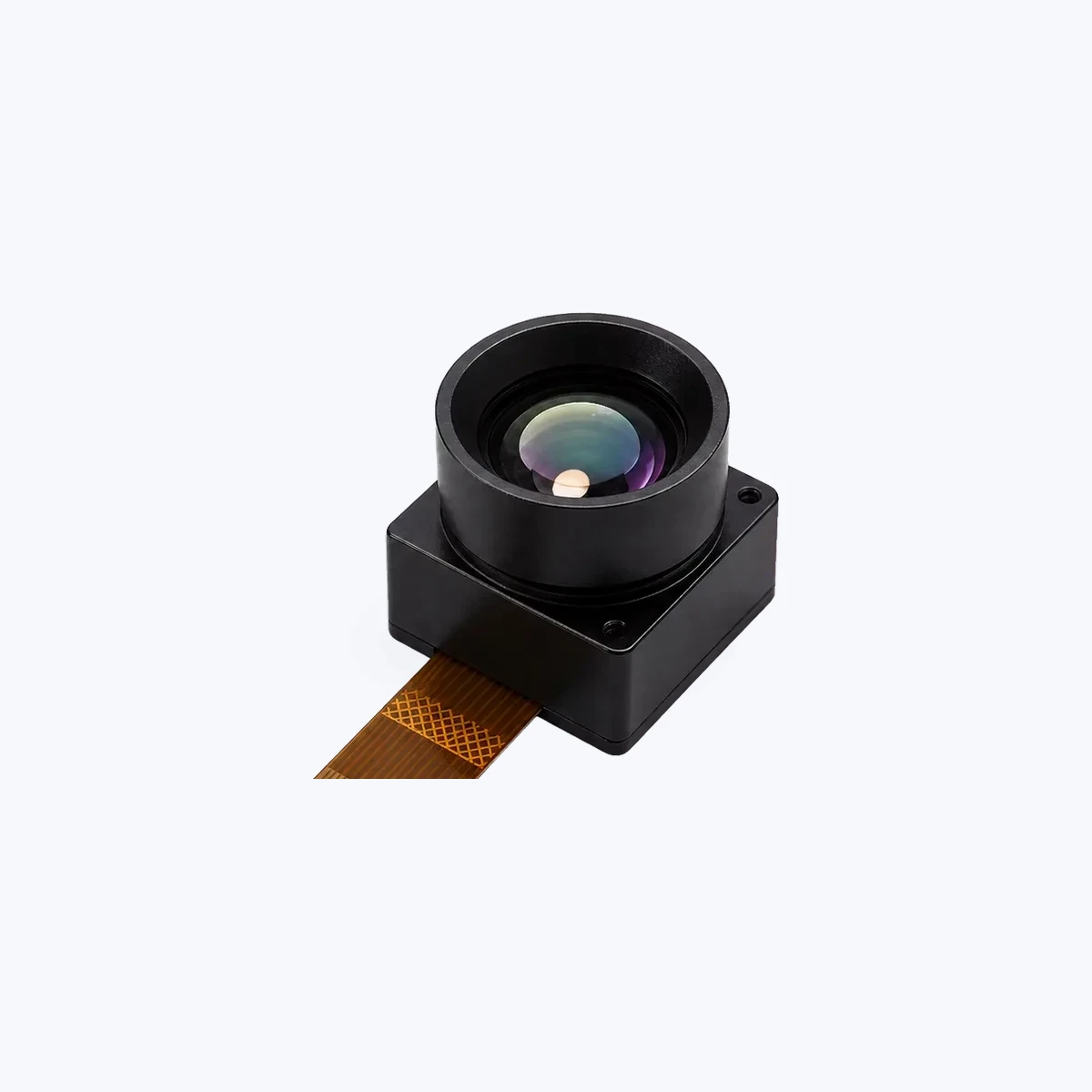
Product Overview: The TC160-NF is a micro-footprint uncooled LWIR thermal imaging module designed specifically for OEM payload integration, embedded vision systems, micro-UAV pods, and low-power sensory arrays. Built with an SPI host interface and engineered around an ultra-efficient 3.3 V rail, it delivers factory-calibrated thermal output in an ultra-lightweight form factor.
OEM Integration Highlights: Drawing only ~76–78 mW, this module is an exceptional fit for secondary blind-spot monitoring on multi-rotors, sub-watt thermal collision avoidance arrays, and auxiliary tactical robotics. Its fixed narrow-FOV optical block delivers clean, focused scene telemetry without loading down the host platform’s battery or flight compute board.
| Specification Parameter | Technical Detail / Parameter Value |
|---|---|
| Product Model & SKU | TC160-NF / SKU Reference: MI1602M5S |
| Detector Class & Resolution | Uncooled LWIR Module | 160 x 120 pixels (19,200 total pixels) |
| Detector Pitch & Spectral Range | 35 µm reference | 8–14 µm (Long-Wave Infrared) |
| Max Frame Rate | Up to 25 FPS |
| Field of View (FOV) | 56° / 45° / 34° (Diagonal / Horizontal / Vertical) |
| Optical Path | Narrow-FOV fixed optical configuration |
| Host Interface & Connector | SPI Host Interface | 10-pin FPC (0.5 mm pitch reference) |
| Supply Voltage & Power Consumption | 3.3 V Supply | Ultra-low-power (~76–78 mW reference) |
| Operating Temperature & Calibration | -20°C to +85°C | Factory-calibrated thermal output |
Handheld Infrared Thermal Observation Instrument
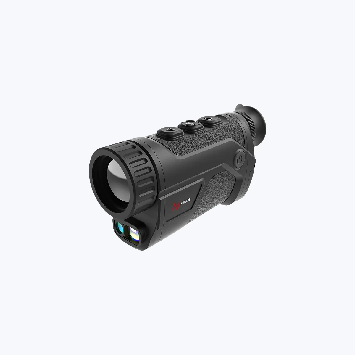
Product Overview: The Handheld Infrared Thermal Observation Instrument is a ruggedized field system built for ground operators, environmental surveillance teams, public safety squads, and infrastructure auditors requiring immediate ground-truth verification. It features selectable dual-resolution sensor configurations paired with fast F/1.0 optics in a balanced, impact-resistant chassis.
Operational Deployment Fit: This unit acts as the primary ground companion to thermal drone sweeps. When an aerial drone identifies a potential hot spot or perimeter breach, ground teams deploy this instrument to verify the target at ground level. With native 50 Hz frame rates, an industry-leading NETD of ≤20 mK, and an ergonomic ~550 g housing, it provides high-contrast thermal imaging under the toughest field conditions.
| Specification Parameter | Technical Detail / Parameter Value |
|---|---|
| Sensor Core Architecture | VOx uncooled microbolometer sensor (8–14 µm spectral band) |
| Resolution Options | 384 x 288 @ 12 µm / 640 x 512 @ 12 µm configuration paths |
| Pixel Pitch & Frame Rate | 12 µm pixel pitch | 50 Hz real-time native frame rate |
| Thermal Sensitivity (NETD) | ≤ 20 mK (@25°C, F#1.0, 25 Hz) |
| Objective Lens Options | 25 mm / 35 mm / 50 mm F1.0 fast optical paths |
| Chassis Weight Class | Approx. 550 g weight class for mobile workflows |
| Core Workflows | Outdoor monitoring, Search & Inspection, Field Survey, Industrial Awareness |
Direct Architectural Comparison: Core Module vs. Field Instrument
When architecting a comprehensive thermal imaging capability, defense and industrial procurement teams must establish where each system tier fits within the mission lifecycle. The table below delineates the structural differences between bare OEM integration cores and complete observation instruments:
| Architecture Dimension | TC160-NF LWIR OEM Module | Handheld Thermal Observation Instrument |
|---|---|---|
| System Form Factor | Board-level micro-sensor module | Fully enclosed, ruggedized field instrument |
| Host Interface | 10-pin FPC (SPI digital bus) | Integrated display, ergonomic controls & battery |
| Power Requirement | 3.3 V DC input (~76–78 mW) | Internal battery system for prolonged field runtimes |
| Spatial Resolution | 160 x 120 pixels (35 µm pitch) | 384 x 288 or 640 x 512 pixels (12 µm pitch) |
| Optical Configuration | Fixed narrow-FOV (56° DFOV) | Selectable 25 mm / 35 mm / 50 mm F1.0 lenses |
| UAS Operational Tier | Embedded collision sensing & sub-watt payloads | Ground-truth anomaly validation & perimeter monitoring |
6. System Integration Workflows, Compliance & Procurement Guidelines
Getting thermal sensor payloads successfully integrated into industrial drones takes disciplined mechanical balancing, clean electrical isolation, and careful attention to trade compliance.
Mechanical Gimbal Balancing & Mass Distribution
Holding steady thermal video on a long 50 mm focal length requires exact static balancing across the 3-axis brushless gimbal. Because Germanium lenses are heavy, the payload Center of Gravity (CoG) is pulled heavily toward the front optical elements.
Follow this standard bench procedure across all three axes:
- ⚙️ Pitch Axis Neutral Balance: With gimbal motors powered off, tilt the camera to any arbitrary angle (+90° down to -90° up). The assembly must remain stationary. If the lens tips forward or back, slide the longitudinal baseplate until you hit pure neutral balance.
- ⚙️ Roll Axis Symmetry: Align the lateral center of mass directly with the roll motor shaft. If the camera leans laterally, the roll motor is forced to pull continuous holding current, generating heat and causing micro-jitter in the video stream.
- ⚙️ Vibration Isolation Tuning: Uncooled microbolometers pick up high-frequency motor harmonics from drone props (generally 100 Hz to 400 Hz). Your gimbal isolation plate must use silicone dampening grommets matched precisely to the payload AUW to isolate the sensor array from mechanical resonance.
Regulatory Compliance: NDAA, Dual-Use, and ITAR Considerations
Because high-performance thermal sensors are dual-use technologies, sourcing teams must navigate strict legal and compliance frameworks:
- ✅ NDAA Compliance (National Defense Authorization Act): For US enterprise, municipal, and defense contracts, thermal payloads must comply with Section 884/889 rules. This bans video surveillance and telecom hardware from covered Chinese manufacturers. Sourcing NDAA-compliant cores guarantees your completed platform is eligible for critical infrastructure and government tenders. We detail these exact submission standards in our guide on NDAA Compliance & Thermal Camera RFQ Documentation.
- ✅ Dual-Use Export Controls: Any thermal core running at ≥9 Hz native frame rate falls under international Dual-Use Export Control classifications (such as Wassenaar Arrangement Category 6A003.b.4). Systems integrators must maintain clean end-user statements, import authorizations, and non-re-export paperwork before international shipping.
- ✅ Non-ITAR Supply Chains: Sourcing non-ITAR thermal cores frees commercial drone manufacturers to sell their completed airframes internationally without getting tied up in US International Traffic in Arms Regulations licensing delays.
RFQ Engineering Checklist for Drone Payload Procurement
To avoid integration delays and get accurate quotes from component vendors, provide the following parameters in your initial Request for Quotation (RFQ):
Pre-Procurement Technical Checklist
- Target Detector Resolution: 160×120 (obstacle sensing), 384×288 (general inspection), or 640×512 (tactical/long-range DRI).
- Output Data Pipeline: 8-bit AGC video stream vs. 14-bit/16-bit raw radiometric counts for direct onboard temperature measurement.
- Optical Focal Length & FOV: Required standoff distance, target Ground Sampling Distance (GSD), and lens options (e.g., 25 mm, 35 mm, 50 mm).
- Electrical & Bus Protocols: Physical bus interface (SPI, MIPI-CSI2, Parallel, USB) and voltage limits (e.g., 3.3 V sub-100 mW power budget).
- Operating Environmental Profile: Temperature range (-20°C to +85°C), enclosure sealing (IP65/IP67), and mechanical vibration damping profiles.
- Compliance Documentation: Certificate of Origin, NDAA compliance declaration, and export clearance documentation.
When you are ready to review system specs with an applications engineer, submit your parameters directly through the Camcuda Engineering & RFQ Portal.
7. Deep-Dive Engineering FAQ: Thermal UAV Payloads
What are the primary technical bottlenecks when integrating a custom infrared camera into a drone platform?
How should procurement teams choose between 384×288 and 640×512 thermal cores for drone payloads?
Is it more cost-effective to buy turnkey infrared drones or build custom payloads using OEM thermal cores?
📚 References & Further Reading
- Industry Standard: Edge-AI Acceleration & Embedded Computing — NVIDIA JetPack SDK
- Industry Standard: Commercial UAV Industry Market Analysis — Commercial UAV News
- Related Guide: Supply Chain & Export Compliance — NDAA Compliance & Thermal Camera RFQ Documents
- System Catalog: Thermal Imaging Cores & Tactical Systems — Camcuda Product Overview
- Technical Support: Applications Engineering & Custom Integrations — Camcuda Engineering RFQ Portal