Thermal UAV Payload Integration Guide: Choosing OEM Cores for Aerial Inspection
Thermal UAV Payload Integration Guide: Choosing OEM Cores for Aerial Inspection
Designing an aerial thermography payload is a brutal exercise in balancing physics, aerodynamics, electrical noise isolation, and embedded edge compute. In the shop, aerospace engineers, commercial drone builders, and payload integrators face unforgiving operational constraints. Every single gram of parasitic dead weight you bolt onto a stabilized gimbal eats directly into battery endurance, destabilizes flight dynamics in choppy air, and pushes brushless motor PID control loops to their absolute limits. At the same time, cheaping out on optical spatial resolution or microbolometer sensitivity just to save mass leaves you with an airborne sensor that can’t reliably resolve sub-surface utility defects, cell-level solar shunts, or subtle building envelope heat leaks from standard flight ceilings.
Look, successfully integrating a thermal UAV (Unmanned Aerial Vehicle) payload is way more complex than just clamping a cased thermal camera under an airframe and hoping for the best. A professional integration workflow demands precise calculations of ground sample distance across target altitudes, clean DC power distribution isolated from violent electronic speed controller (ESC) switching noise, deterministic low-latency interfaces (like SPI, MIPI-CSI, USB, or DVP) for companion computer edge AI, and bulletproof handling of radiometric calibration drift caused by turbulent prop-wash. This comprehensive technical guide lays out the field-proven engineering principles, core math, and hardware selection criteria needed to build and deploy Long-Wave Infrared (LWIR) OEM cores and multi-spectral sensors on commercial airframes.
Table of Contents
- 👉 1. Spatial Resolution Physics: Optics, Altitude, and Ground Sample Distance (GSD)
- 👉 2. SWaP-C Optimization & Gimbal Design
- 👉 3. Hardware Interfaces & Edge Computing Architectures
- 👉 4. Radiometric Calibration, NUC, and Aerodynamic Drift
- 👉 5. Sensor Fusion: Aerial Payloads vs. Ground Truth Systems
- 👉 6. Comprehensive Product Showcase & OEM Hardware Comparison
- 👉 7. Integration & Deployment FAQ
1. Spatial Resolution Physics: Optics, Altitude, and Ground Sample Distance (GSD)
The number one point of failure in aerial thermography boils down to bad spatial resolution on the target surface. When an uncooled Long-Wave Infrared (LWIR) focal plane array operates at common civil aviation flight ceilings—typically anywhere from 30 meters to 120 meters Above Ground Level (AGL)—the physical footprint of the defect must cover a sufficient number of active detector pixels. If you don’t ensure adequate pixel coverage, the sensor averages the target temperature with surrounding ambient surfaces, yielding wildly inaccurate temperature values or causing inspectors to miss critical structural faults entirely.
The Geometric Mathematics of Aerial Thermography
To spec out your lens assembly and sensor core without guesswork, calculate the Instantaneous Field of View (IFOV) and the resulting Ground Sample Distance (GSD). The core geometric equations governing infrared sensor optics are straightforward:
IFOV = p / f | GSD = (p × H) / f = IFOV × H
Here is what those variables mean in the field:
- ⚙️ GSD: Ground Sample Distance (measured in millimeters or centimeters per pixel on the ground target).
- ⚙️ p: Physical detector pixel pitch (commonly 12 µm, 17 µm, or 35 µm in uncooled microbolometers).
- ⚙️ f: Effective focal length of the germanium optical lens assembly (in millimeters).
- ⚙️ H: True flight altitude above the target plane (in meters AGL).
- ⚙️ IFOV: Instantaneous Field of View for an individual detector element (in milliradians).
Here’s the deal: while GSD tells you the physical patch of ground an individual pixel represents, non-destructive testing standards—such as protocols established by the ASNT Thermal/Infrared Testing committee—make it clear that bare detection does not equal an accurate radiometric measurement. Optical diffraction, lens aberrations, and the sensor Modulation Transfer Function (MTF) mean a hot spot must span several adjacent pixels before you hit true radiometric temperature convergence.
In practice, integrators must calculate the Measurement Instantaneous Field of View (MFOV), which demands an absolute minimum projection of 3 × 3 to 4 × 4 contiguous detector pixels across the target:
MFOV ≈ 3 × IFOV to 4 × IFOV
If an electrical substation clamp, solar bypass diode, or building insulation crack covers fewer pixels than your MFOV threshold, your recorded thermal data turns into a mathematical blend of the target and its background, wrecking your diagnostics. To dive deeper into microbolometer formats and lens pairings, check out our in-depth engineering review on uncooled LWIR thermal modules for industrial monitoring.
| Inspection Profile | Operating Altitude (AGL) | Target Dimensions | Minimum Recommended Array | Optical Path Requirement |
|---|---|---|---|---|
| Close Industrial & HVAC Audit | 5 m – 15 m | 5 cm – 15 cm | 160 × 120 / 256 × 192 | Wide Field (45° – 56° FOV) |
| Rooftop Solar & Substation Scan | 20 m – 50 m | 2 cm – 5 cm | 384 × 288 / 640 × 512 | Medium Field (25° – 35° FOV) |
| Utility Transmission & Grid Survey | 50 m – 120 m | 1 cm – 3 cm | 640 × 512 / 1280 × 1024 | Narrow Telephoto (10° – 15° FOV) |
2. SWaP-C Optimization & Gimbal Design
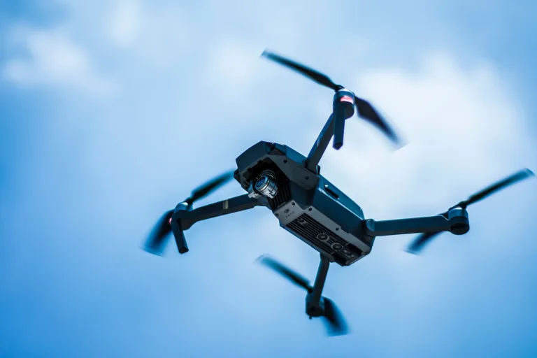
In the unmanned aerospace world, Size, Weight, Power, and Cost (SWaP-C) dictate your operational envelope. Packing a thermal imager onto a multirotor or fixed-wing platform requires aggressive power budgeting, thermal dissipation paths, and strict center-of-gravity (CG) balancing.
Mass Budgets and Gimbal Inertia
Fully packaged handheld thermal imagers come encased in thick aluminum, heavy rubber overmolding, bulky lithium-ion packs, and dedicated display panels. These complete units easily tip the scales at 500 to 1,000+ grams. Trying to strap a handheld device onto an aerial gimbal creates massive integration headaches:
- ⚠️ Flight Endurance Penalties: Every 100 grams of dead payload mass forces your motors to pull higher continuous current from the flight pack, slashing hover time and survey acreage by up to 30% to 50%.
- ⚠️ Rotational Inertia & Sizing: Bulky housings demand oversized, high-torque brushless gimbal motors. That increased mass moment of inertia makes loop tuning painful, leading to high-frequency jitter during fast maneuvers or gusty winds.
- ⚠️ Aerodynamic Drag: Large enclosures present a massive cross-section to prop-wash and headwinds, driving unwanted oscillations that standard gimbal stabilization loops struggle to damp out.
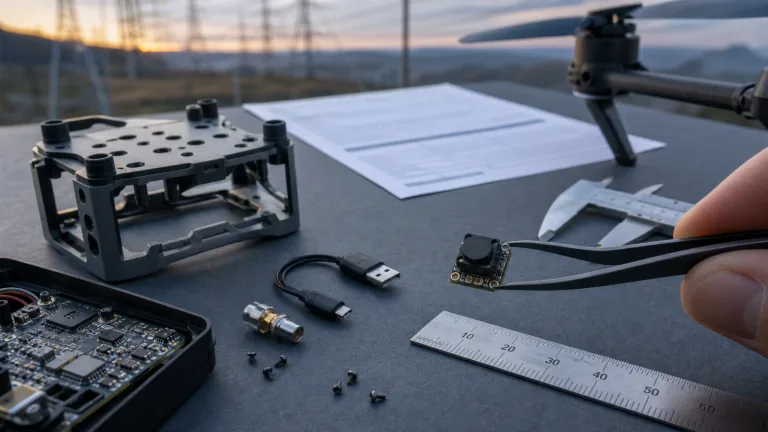
Bare OEM thermal imaging cores eliminate those failure points by stripping out user interfaces, batteries, and outer casings. A bare core weighing under 20 to 50 grams drops cleanly into micro-stabilized direct-drive 2-axis or 3-axis gimbals, preserving aerodynamic efficiency and maximizing your flight windows.
Power Delivery and Electrical Noise Mitigation
Drones are electronically noisy environments. Multi-cell lithium-polymer (LiPo) batteries (typically 4S to 12S setups) suffer severe voltage sag under load, paired with nasty high-frequency switching ripple generated by brushless Electronic Speed Controllers (ESCs). Uncooled LWIR microbolometers are exceptionally sensitive to power rail ripple; unmitigated supply noise shows up immediately as horizontal banding, fixed-pattern noise (FPN), and radiometric drift across your frames.
Payload engineers need dedicated, isolated power conversion. The clean setup involves a high-efficiency DC-DC buck step-down regulator followed directly by a low-dropout (LDO) linear regulator with high Power Supply Rejection Ratio (PSRR). This delivers an ultra-clean, ripple-free 3.3V DC rail to the thermal core. Ground planes must be decoupled using ferrite beads to prevent motor ground bounce from corrupting high-speed SPI or MIPI data lines.
3. Hardware Interfaces & Edge Computing Architectures
Modern aerial thermography is moving fast toward automated anomaly detection directly onboard the UAV. Instead of simply pushing a downscaled analog video feed down to a ground monitor, engineers mount companion computers—such as NVIDIA Jetson Orin modules or Raspberry Pi Compute Module 4 (CM4) boards—to crunch radiometric data in real time.
| Host Interface Protocol | Radiometric Depth | Latency Profile | Compute Overhead | Hardware Integration Complexity |
|---|---|---|---|---|
| SPI (Serial Peripheral Interface) | Full 14-bit / 16-bit Raw | Sub-10 ms (Deterministic) | Low to Moderate | Simple 10-pin FPC / Direct Microcontroller Bus |
| MIPI-CSI-2 | Full 14-bit / Raw Bayer/YUV | < 2 ms (Ultra-Low) | Minimal (Zero-Copy DMA) | High (Impedance-matched differential routing) |
| USB 2.0 / UVC | Processed YUV / Encapsulated Raw | 15 ms – 40 ms | Moderate (Driver Stack) | Plug-and-Play Standard Connector |
| Analog CVBS / PAL | None (Visual AGC Only) | < 1 ms | Zero (Direct RF Transmitter) | Legacy 2-Wire Coaxial Line |
Embedded Software Integration (ROS, MAVLink, and V4L2)
To deploy an autonomous fault detection pipeline, feed your raw thermal frames straight into embedded vision frameworks. Advanced setups, like those covered in Vision Systems Design, leverage lightweight edge neural nets (such as YOLOv8-nano) to detect hotspots, gas leaks, or structural insulation failures on the fly.
In standard drone builds, the software stack executes across three distinct stages:
- ⚙️ Frame Ingestion & Radiometric Parsing: The edge computer pulls raw 14-bit digital numbers (DN) over high-speed SPI or MIPI Direct Memory Access (DMA). Firmware calibration matrices convert each DN value into absolute temperature units (Kelvin or Celsius) using onboard thermistor telemetry:
T_pixel = f(DN_raw, T_fpa, T_lens_housing)
- ⚙️ Real-Time AI Inference: The calibrated frame feeds as a normalized floating-point array straight into a TensorRT inference engine. The network isolates anomalies, highlighting localized thermal deltas (ΔT ≥ 15°C over ambient baseline).
- ⚙️ Spatial Geotagging via MAVLink / ROS: The vision pipeline talks to the flight controller (running PX4 or ArduPilot) over a serial MAVLink connection. Real-time RTK positioning, AGL altitude, and gimbal pitch/yaw values get written directly into the thermal frame’s EXIF metadata or streamed back to the Ground Control Station (GCS).
4. Radiometric Calibration, NUC, and Aerodynamic Drift
Uncooled microbolometer arrays—whether fabricated using Vanadium Oxide (VOx) or Amorphous Silicon (α-Si)—are thermal resistors that absorb infrared radiation and change electrical resistance. Because the sensor housing and optical elements change temperature during flight, keeping your thermal calibration stable is an ongoing engineering challenge.
Aerodynamic Prop-Wash and Convective Drift
During flight, propeller downwash blasts high-velocity, turbulent air right across the gimbal payload. Climbing or descending rapidly exposes the payload to sharp ambient temperature swings (easily shifting 5°C to 15°C in minutes). These dynamics trigger rapid shifts in the focal plane array substrate temperature ($T_{\text{fpa}}$) and lens barrel ($T_{\text{lens}}$), creating non-uniform thermal drift across the microbolometer array.
Non-Uniformity Correction (NUC) Mechanisms
To eliminate Spatial Fixed-Pattern Noise (FPN) and maintain temperature accuracy, thermal cameras run Non-Uniformity Correction (NUC):
- ⚙️ Mechanical Shutter NUC: A tiny motorized mechanical shutter drops in front of the array for 200 ms to 500 ms, giving the sensor an optically uniform thermal reference to calculate new pixel offset corrections. It’s highly accurate, but that physical shutter adds moving parts, increases core mass, and introduces a momentary video freeze that can break target-tracking algorithms or autonomous visual flight loops.
- ⚙️ Shutterless Algorithmic NUC: Modern OEM modules use dynamic mathematical models. Thermistors positioned across the optical path and sensor substrate feed continuous temperature updates to firmware lookup tables (LUTs). This delivers a continuous, freeze-free video stream ideal for high-speed tracking and obstacle avoidance.
For more details on calibration engineering and factory look-up tables, explore our technical library in the thermal imaging guides category.
5. Sensor Fusion: Aerial Payloads vs. Ground Truth Systems
Industrial inspections work best as a two-stage process. An airborne thermal UAV runs wide-area sweeps across acres of infrastructure in minutes, while ground crews use rugged handheld imagers for close-range verification and formal reporting.
Multi-Spectral Fusion Principles
While standalone LWIR is unbeatable for spotting temperature differentials, thermal imagery lacks fine edge detail, texture, and legible text. Dual-light fusion systems solve this by combining two separate spectra:
- ✅ Long-Wave Infrared Channel (8–14 µm): Measures pure emissive thermal radiation, pinpointing sub-surface heat buildup, overloaded breakers, and insulation voids in pitch-black conditions.
- ✅ Visible / Low-Light CMOS Channel (400–900 nm): Gathers high-contrast reflected light, providing crisp physical borders, asset tags, structural wirelines, and fine textural detail.
Onboard Image Signal Processors (ISPs) run high-pass edge detection (like Sobel or Laplacian operators) on the visible feed, pull out the high-contrast structural outlines, and geometrically overlay them onto the false-color LWIR image. This allows ground crews or remote operators to instantly read serial numbers, warning labels, and component boundaries directly over the thermal heat map.
6. Comprehensive Product Showcase & OEM Hardware Comparison
Selecting the right thermal hardware means matching physical specs to your specific deployment tier. Below, we break down two industrial-grade instruments: an ultra-lightweight bare OEM module built for embedded drone payloads, and a ruggedized dual-light handheld observer built for ground-truth verification and site surveys.
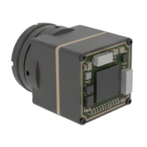
TC160-NF 160×120 Uncooled LWIR Thermal Imaging Module
Primary Integration Profile: Ultra-lightweight bare OEM thermal core designed for companion computers, embedded aerial payloads, smart sensing platforms, and SWaP-constrained industrial systems.
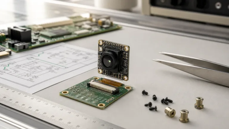
The TC160-NF is an ultra-compact, uncooled Long-Wave Infrared (LWIR) module engineered specifically for OEM developers who need clean radiometric thermal data in a micro footprint. Operating across the standard 8–14 µm band at up to 25 FPS, the core interfaces over an SPI host bus via a 10-pin 0.5 mm pitch Flexible Printed Circuit (FPC) connector. Drawing just 76–78 mW on a direct 3.3V DC rail, this bare module drops into micro-gimbals and tight drone enclosures without killing battery life or causing thermal throttling issues.
| Detector Specifications | |
|---|---|
| Product Model / SKU | TC160-NF / MI1602M5S |
| Detector Architecture | Uncooled LWIR Microbolometer Module |
| Thermal Resolution | 160 × 120 (19,200 active pixels) |
| Pixel Pitch & Spectral Band | 35 µm reference | 8 – 14 µm LWIR |
| Maximum Frame Rate | Up to 25 FPS |
| Optics & Field of View | |
| Optical Path Configuration | Narrow-FOV fixed optical assembly |
| Field of View (FOV D/H/V) | 56° Diagonal / 45° Horizontal / 34° Vertical |
| Electrical & Mechanical Parameters | |
| Supply Voltage & Power | 3.3 V DC supply | ~76 – 78 mW low-power operation |
| Host Interface & Connector | SPI host interface | 10-pin FPC (0.5 mm pitch) |
| Operating Temperature & Cal | -20°C to +85°C reference | Factory calibrated thermal output |
CAMCUDA Ura-Z Dual-Spectrum Handheld Thermal Viewer
Primary Integration Profile: High-resolution handheld multi-spectral observation device for ground-truth verification, outdoor search, perimeter security, and site documentation.
The Ura-Z Series is a rugged dual-light handheld thermal observer designed to give field inspectors crisp multi-spectral imagery and solid radiometric verification in harsh environments. Featuring a 640×512 uncooled thermal detector with a fine 12 µm pixel pitch, it pairs with a 35 mm manual-focus lens providing a 12.6° × 10.1° Field of View. The Ura-Z blends thermal and low-light visible feeds on a single display, letting technicians instantly confirm anomalies spotted from the air. Wrapped in an IP66-rated housing weighing under 1 kg and rated from -40°C to +50°C, it’s an essential handheld companion for aerial inspection teams.
| Key Technical Parameters | |
|---|---|
| Product Family | Ura-Z Series Dual-Light Fusion Observer |
| Observation Modes | Dual-light fusion (Thermal + Low-Light Visible enhancement) |
| Thermal Resolution | 640 × 512 |
| Pixel Pitch | 12 µm |
| Lens Configuration | 35 mm manual focus lens |
| Field of View (FOV) | 12.6° × 10.1° |
| Ingress Protection | IP66 ruggedized field housing |
| Operating Temperature | -40°C to +50°C |
| Dimensions & Weight | ≤ 153 × 150 × 68 mm | ≤ 1 kg complete handheld mass |
Direct Architectural Comparison
| Engineering Parameter | TC160-NF Bare OEM Module | Ura-Z Series Handheld Observer |
|---|---|---|
| Form Factor Class | Bare-board OEM thermal core | Complete ruggedized handheld device |
| Primary Operational Role | UAV gimbal payload / Embedded AI sensing | Ground-truth verification / Site documentation |
| Sensor Resolution & Pitch | 160 × 120 (35 µm pitch) | 640 × 512 (12 µm pitch) |
| Spectral Modality | Uncooled LWIR (8–14 µm) | Dual-light (LWIR + Low-Light Visible fusion) |
| Optical Field of View | 45° Horizontal (56° Diagonal) | 12.6° × 10.1° (35 mm Telephoto) |
| Power Consumption | 76 – 78 mW (Direct 3.3V rail) | Internal battery system / DC charging |
| Physical Mass | < 15 grams (Ultra-light core) | ≤ 1000 grams (Field ruggedized) |
| Host Connectivity | SPI bus / 10-pin FPC interface | Integrated display / External export ports |
To explore our full lineup of commercial imaging instruments, browse our catalog of thermal observation devices, or check out our application breakdown for outdoor field thermal imaging.

7. Integration & Deployment FAQ
Why is image resolution often insufficient when using a thermal UAV for utility-scale solar farm inspection?
What data interface is best suited for connecting a thermal core to an onboard companion computer?
How do airframe motor vibrations and prop-wash turbulence impact uncooled thermal sensors?
What export controls and regulatory compliances apply to OEM thermal cores and thermal UAV platforms?
For custom engineering consultations, OEM integration schematics, or volume component quotations, reach out directly through our engineering RFQ portal or check out our latest teardowns on our industrial thermal imaging blog.
📚 References & Further Reading
- Industry Standard: ASNT Thermal/Infrared Testing
- Industry Standard: Vision Systems Design
- Related Guide: Uncooled LWIR Thermal Modules for Outdoor Security & Industrial Monitoring
- Related Guide: CamCuda Thermal Imaging Technical Guides