 1 / 7
1 / 7CAMCUDA AeroMini 640×512 Uncooled LWIR USB Thermal Camera Core for UAV Integration
Price range: $399.00 through $770.43Inquiry-only lens options: Request a quote
640 × 512 uncooled VOx LWIR core for UAV payload integration. Non-radiometric: 60 Hz factory default, optional 30 Hz factory configuration at the same price. Radiometric: 25 Hz, availability enquiry only. Select the camera version, frame rate, lens and interface below.
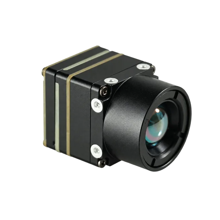
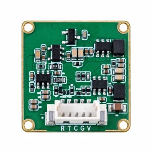
Product photography: select 9, 13, 25 or 35 mm to view the corresponding photographed assembly and hand-held views. Backgrounds have been removed for a consistent presentation. Interface boards vary by configuration; confirm the ordered assembly. The separate 3D preview represents the 7 mm model.
Skonfiguruj i kup
Wybierz swoją konfigurację
Sprawdź aktualną cenę jednostkową online, a następnie przejdź do kasy lub poproś o wycenę OEM.
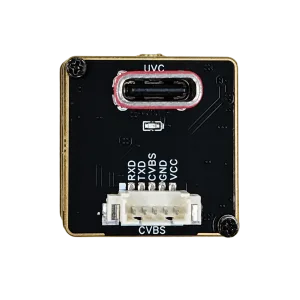
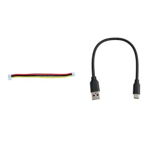
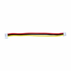
Included in your kit
Aktualnie brak w magazynie. Cena niedostępna.
Zapytaj o dostępnośćZakup online oraz zamówienia przedsprzedażowe nie są dostępne dla tej wersji.
Obiektyw / wygląd wyłącznie w celach poglądowych. Moduł radiometryczny wymaga potwierdzenia.
Potwierdzanie konfiguracji…
Wybierz wersję kamery. Obrazowanie nieradiometryczne nie mierzy temperatury.
Szybka płatność
Ceny OEM i ilościowe
Weryfikacja konfiguracji dla projektów niestandardowych i zamówień produkcyjnych.
Cena została potwierdzona dla wybranej konfiguracji.
Omów konfigurację niestandardowąOpis
PRODUCT DOCUMENTATION
Karta katalogowa AeroMini 640
Specifications, lens options and interface connections.
ENGINEERED FOR INTEGRATION
Compact thermal vision.
Configured for your payload.
CAMCUDA AeroMini 640 combines a 640 × 512 uncooled VOx detector with a compact core for UAV payloads, DJI-type platforms and custom gimbals. Choose 60 Hz or 30 Hz factory configuration for non-radiometric imaging, or enquire about the 25 Hz radiometric version.
VISIBLE LIGHT & THERMAL IMAGING
See rain droplets on clothing.
Rain droplets on clothing, seen in thermal and visible light.
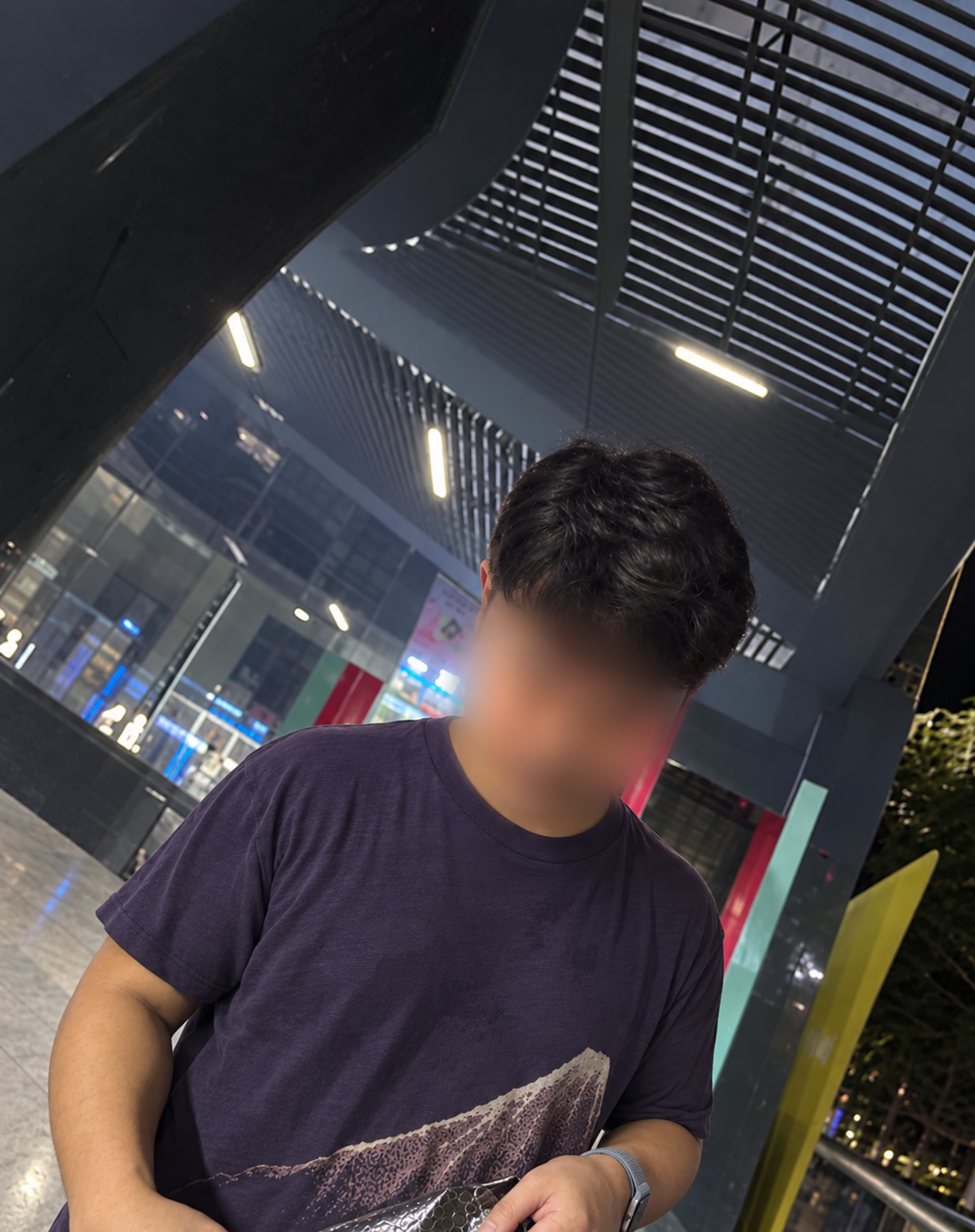 Corresponding clothing area
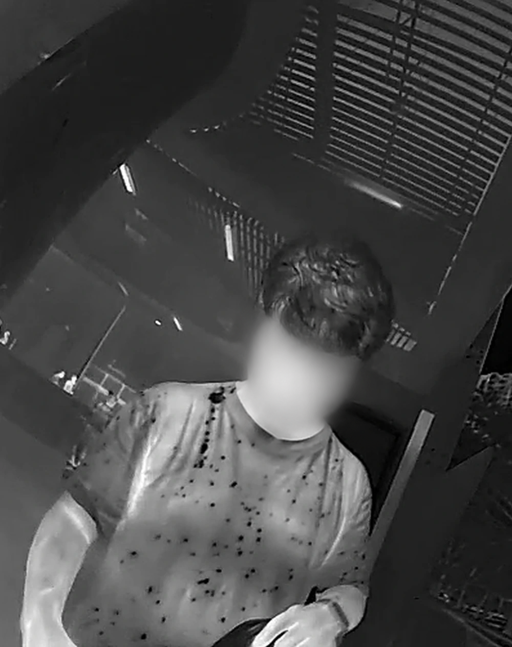 Rain droplets & wet areas
Drag to compare · Use arrow keys for precise control
Rain droplets and wet areas produce the visible spot pattern in this thermal image; no temperature values are inferred. Faces anonymized for privacy.
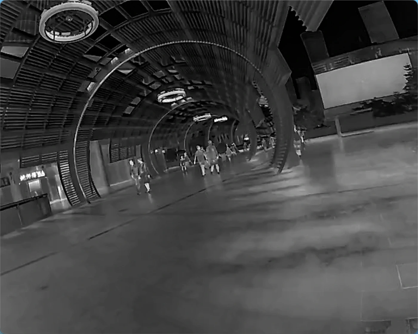
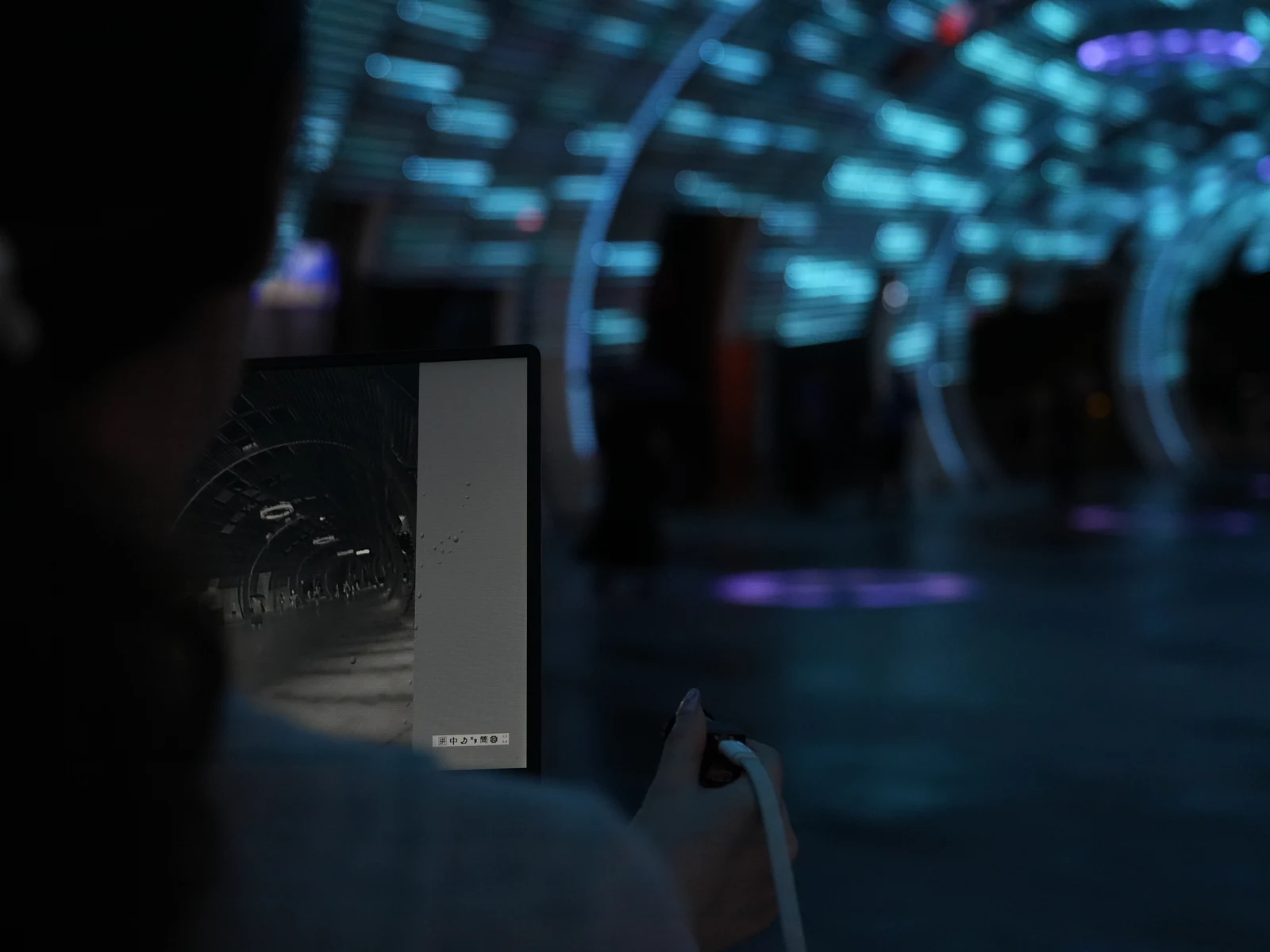
CAMCUDA FIELD CAPTURE · SHENZHEN BAY
Real surroundings. Real thermal imagery.
Captured by CAMCUDA at Shenzhen Bay with AeroMini 640 · 9 mm.
Dane techniczne
Choose the camera version and interface board for your integration. Temperature measurement applies only to the radiometric version.
| Parametr | Specification | Configuration notes |
|---|---|---|
| Rozdzielczość | 640 × 512 | Both versions |
| Typ detektora | VOx | Uncooled detector |
| Klatkaż — nieradiometryczny | 60 Hz default / 30 Hz factory option | Factory default 60 Hz; select 30 Hz when ordering. |
| Klatkaż — radiometryczny | 25 Hz | Radiometric version only; availability enquiry. |
| Rozmiar piksela | 12 μm | Both versions |
| Odpowiedź widmowa | 8–14 μm | Long-wave infrared |
| NETD | ≤30 mK at 25 °C, F/1.0 | At 25 °C, F/1.0 |
| Liczba przysłony | 1 | Both versions |
| Polaryzacja | White hot / Black hot | Selectable image polarity |
| Napięcie zasilania — tabela rodziny produktów | 5 V or 12 V | Board-dependent. The illustrated POWER_IN1 / POWER_IN2 pins are 5 V inputs; do not connect these pins to 12 V. |
| Typowy pobór mocy przy 25 °C | <0,5 W | Typical module consumption; complete-kit consumption may differ. |
| Wideo cyfrowe | YUV, USB, BT.656 | Board and firmware dependent. Confirm host compatibility. |
| Wideo analogowe | CVBS, PAL, NTSC | Output availability depends on the selected board. |
| Komunikacja szeregowa | UART, RS232, RS422 | Availability depends on the selected interface board. |
| Masa, bez obiektywów i kołnierzy | <20 g | Excludes lens and flange. |
| Wymiary, bez obiektywów i kołnierzy | 21 × 21 × 28 mm | Excludes lens and flange; confirm the complete assembly dimensions. |
| Zakres pomiaru temperatury | −20 °C … +550 °C | Radiometric version only. Accuracy and RAW data format require confirmation. |
| Udokumentowane opcje obiektywów radiometrycznych | Tylko 9 / 13 / 18 mm | Radiometric version: 9 / 13 / 18 mm; currently enquiry only. |
| Temperatura robocza | −40 °C … +80 °C | Both versions |
| Temperatura przechowywania | −50 °C … +85 °C | Both versions |
| Wilgotność | 5–95%, bez kondensacji | Non-condensing |
Obiektyw i pole widzenia
Select the field of view for your working distance. Current pricing and availability are shown in the product configurator.
| Model | Ogniskowa | FOV H × V | Wersja kamery |
|---|---|---|---|
| AeroMini 640 · 4 mm | 4 mm | 100° × 82° | Non-radiometric |
| AeroMini 640 · 7 mm | 7 mm | 64° × 52° | Non-radiometric |
| AeroMini 640 · 9 mm | 9 mm | 48.7° × 38.6° | Non-radiometric · Radiometric enquiry |
| AeroMini 640 · 13 mm | 13 mm | 31.9° × 25.7° | Non-radiometric · Radiometric enquiry |
| AeroMini 640 · 15 mm | 15 mm | 29.3° × 23.5° | Enquire about this lens |
| AeroMini 640 · 18 mm | 18 mm | 24.2° × 19.5° | Non-radiometric · Radiometric enquiry |
| AeroMini 640 · 25 mm | 25 mm | 17.5° × 14° | Non-radiometric |
| AeroMini 640 · 35 mm | 35 mm | 12.5° × 10° | Non-radiometric |
| AeroMini 640 · 50 mm | 50 mm | 8.8° × 7° | Non-radiometric |
| AeroMini 640 · 60 mm | 60 mm | 7.3° × 5.9° | Enquire about this lens |
| AeroMini 640 · 75 mm | 75 mm | 5.9° × 4.7° | Enquire about this lens |
Interfejsy i integracja
Check the connector and board revision before wiring. The 16-pin and 26-pin connections below are not a substitute for the matched Type-C board guide.
POWER_IN1 and POWER_IN2 are marked 5 V. Do not connect these pins to 12 V. Confirm the approved input voltage for your selected board.
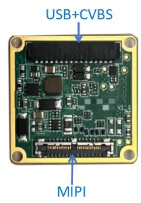
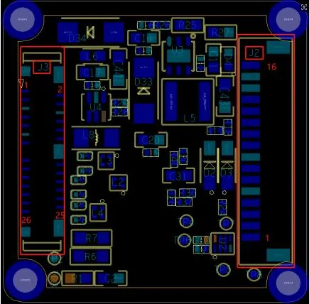
16-pin USB / CVBS connections
Connector: DF52-16S-0.8H. Confirm the connector and board revision before integration.

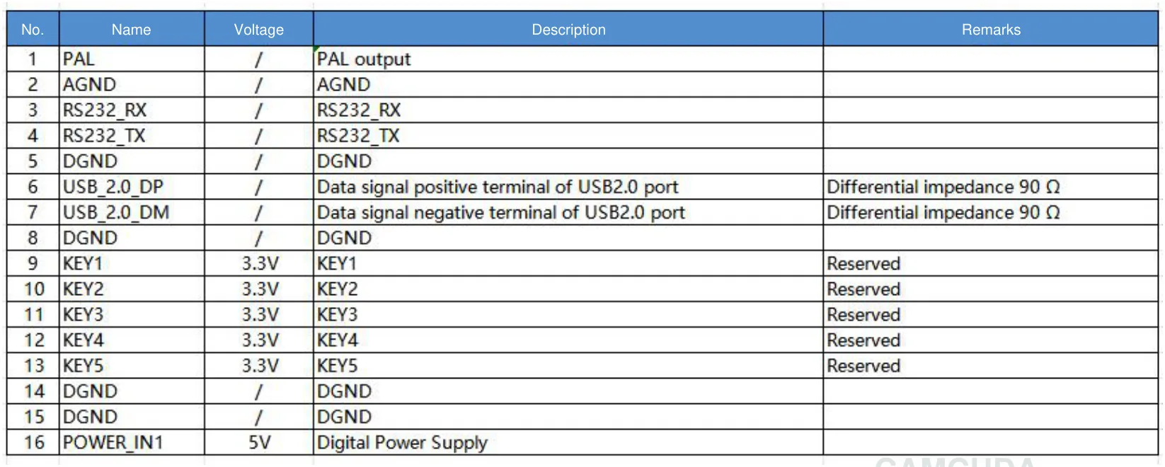
| Pin | Signal | Signal voltage | Opis | Uwagi |
|---|---|---|---|---|
| 1 | PAL | / | Wyjście PAL | |
| 2 | AGND | / | AGND | |
| 3 | RS232_RX | / | RS232_RX | |
| 4 | RS232_TX | / | RS232_TX | |
| 5 | DGND | / | DGND | |
| 6 | USB_2.0_DP | / | Dodatni styk sygnału danych portu USB2.0 | Impedancja różnicowa 90 Ω |
| 7 | USB_2.0_DM | / | Ujemny styk sygnału danych portu USB2.0 | Impedancja różnicowa 90 Ω |
| 8 | DGND | / | DGND | |
| 9 | KEY1 | 3.3V | KEY1 | Zarezerwowane |
| 10 | KEY2 | 3.3V | KEY2 | Zarezerwowane |
| 11 | KEY3 | 3.3V | KEY3 | Zarezerwowane |
| 12 | KEY4 | 3.3V | KEY4 | Zarezerwowane |
| 13 | KEY5 | 3.3V | KEY5 | Zarezerwowane |
| 14 | DGND | / | DGND | |
| 15 | DGND | / | DGND | |
| 16 | POWER_IN1 | 5V | Zasilanie cyfrowe |
“/” indicates that no signal voltage is specified.
26-pin MIPI / DVP connections
Connector: DF56C_26S_0.3V(51). Confirm the connector and board revision before integration.
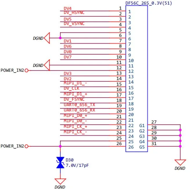
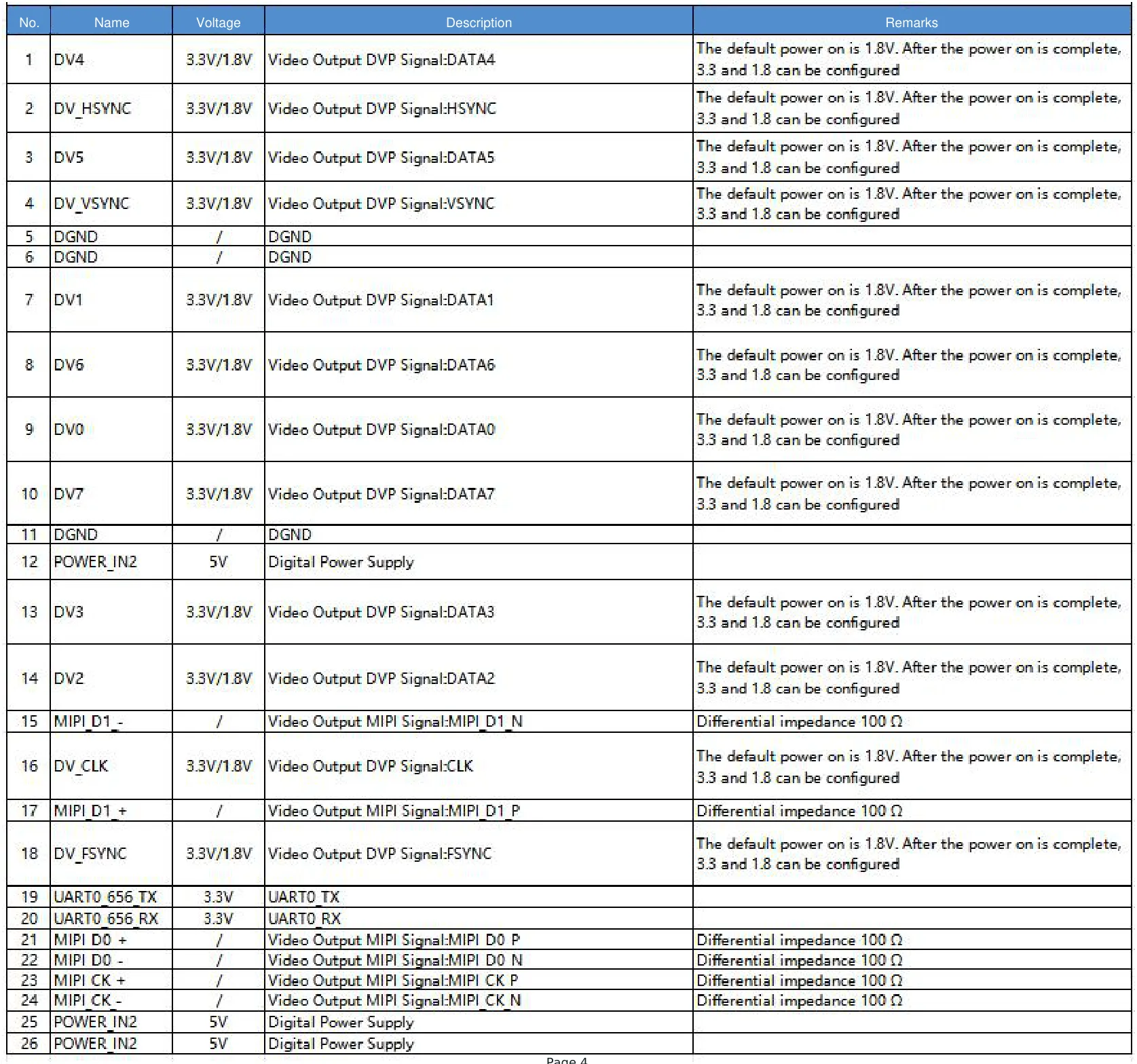
| Pin | Signal | Signal voltage | Opis | Uwagi |
|---|---|---|---|---|
| 1 | DV4 | 3.3V/1.8V | Wyjście wideo DVP Sygnał:DATA4 | Domyślna wartość przy włączeniu zasilania wynosi 1.8V. Po zakończeniu uruchamiania można skonfigurować 3.3 i 1.8 |
| 2 | DV_HSYNC | 3.3V/1.8V | Wyjście wideo DVP Sygnał:HSYNC | Domyślna wartość przy włączeniu zasilania wynosi 1.8V. Po zakończeniu uruchamiania można skonfigurować 3.3 i 1.8 |
| 3 | DV5 | 3.3V/1.8V | Wyjście wideo DVP Sygnał:DATA5 | Domyślna wartość przy włączeniu zasilania wynosi 1.8V. Po zakończeniu uruchamiania można skonfigurować 3.3 i 1.8 |
| 4 | DV_VSYNC | 3.3V/1.8V | Wyjście wideo DVP Sygnał:VSYNC | Domyślna wartość przy włączeniu zasilania wynosi 1.8V. Po zakończeniu uruchamiania można skonfigurować 3.3 i 1.8 |
| 5 | DGND | / | DGND | |
| 6 | DGND | / | DGND | |
| 7 | DV1 | 3.3V/1.8V | Wyjście wideo DVP Sygnał:DATA1 | Domyślna wartość przy włączeniu zasilania wynosi 1.8V. Po zakończeniu uruchamiania można skonfigurować 3.3 i 1.8 |
| 8 | DV6 | 3.3V/1.8V | Wyjście wideo DVP Sygnał:DATA6 | Domyślna wartość przy włączeniu zasilania wynosi 1.8V. Po zakończeniu uruchamiania można skonfigurować 3.3 i 1.8 |
| 9 | DV0 | 3.3V/1.8V | Wyjście wideo DVP Sygnał:DATA0 | Domyślna wartość przy włączeniu zasilania wynosi 1.8V. Po zakończeniu uruchamiania można skonfigurować 3.3 i 1.8 |
| 10 | DV7 | 3.3V/1.8V | Wyjście wideo DVP Sygnał:DATA7 | Domyślna wartość przy włączeniu zasilania wynosi 1.8V. Po zakończeniu uruchamiania można skonfigurować 3.3 i 1.8 |
| 11 | DGND | / | DGND | |
| 12 | POWER_IN2 | 5V | Zasilanie cyfrowe | |
| 13 | DV3 | 3.3V/1.8V | Wyjście wideo DVP Sygnał:DATA3 | Domyślna wartość przy włączeniu zasilania wynosi 1.8V. Po zakończeniu uruchamiania można skonfigurować 3.3 i 1.8 |
| 14 | DV2 | 3.3V/1.8V | Wyjście wideo DVP Sygnał:DATA2 | Domyślna wartość przy włączeniu zasilania wynosi 1.8V. Po zakończeniu uruchamiania można skonfigurować 3.3 i 1.8 |
| 15 | MIPI D1 – | / | Wyjście wideo MIPI Sygnał:MIPI D1 N | Impedancja różnicowa 100 Ω |
| 16 | DV_CLK | 3.3V/1.8V | Wyjście wideo DVP Sygnał:CLK | Domyślna wartość przy włączeniu zasilania wynosi 1.8V. Po zakończeniu uruchamiania można skonfigurować 3.3 i 1.8 |
| 17 | MIPI D1 + | / | Wyjście wideo MIPI Sygnał:MIPI D1 P | Impedancja różnicowa 100 Ω |
| 18 | DV_FSYNC | 3.3V/1.8V | Wyjście wideo DVP Sygnał:FSYNC | Domyślna wartość przy włączeniu zasilania wynosi 1.8V. Po zakończeniu uruchamiania można skonfigurować 3.3 i 1.8 |
| 19 | UART0 656 TX | 3.3V | UART0 TX | |
| 20 | UART0 656 RX | 3.3V | UART0 RX | |
| 21 | MIPI D0 + | / | Wyjście wideo MIPI Sygnał:MIPI D0 P | Impedancja różnicowa 100 Ω |
| 22 | MIPI D0 – | / | Wyjście wideo MIPI Sygnał:MIPI D0 N | Impedancja różnicowa 100 Ω |
| 23 | MIPI CK + | / | Wyjście wideo MIPI Sygnał:MIPI CK P | Impedancja różnicowa 100 Ω |
| 24 | MIPI CK – | / | Wyjście wideo MIPI Sygnał:MIPI CK N | Impedancja różnicowa 100 Ω |
| 25 | POWER_IN2 | 5V | Zasilanie cyfrowe | |
| 26 | POWER_IN2 | 5V | Zasilanie cyfrowe |
“/” indicates that no signal voltage is specified. G1–G5 are connected to DGND; the table lists the 26 signal pins.
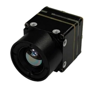
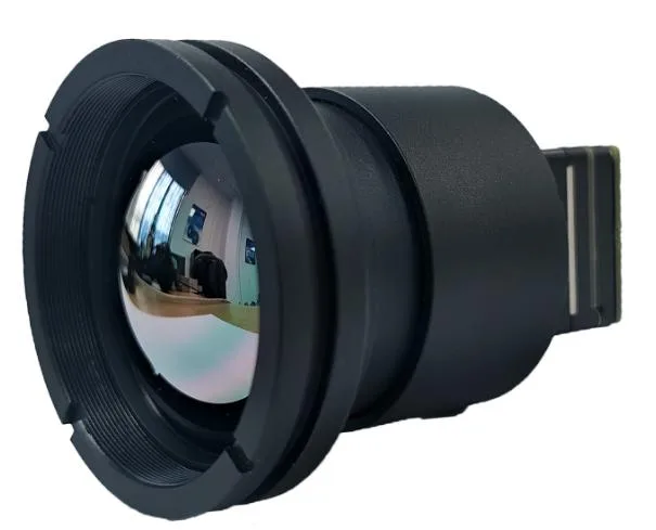
Compact by design
Assembly appearance varies with the lens and interface board. See the selected configuration in the product gallery.
DEVELOPER RESOURCES
Start your integration.
Request the user manual, serial commands and SDK resources for your camera configuration. We will share the matching document package via Google Drive.
AeroMini 640 frequently asked questions
Jaka jest różnica między dwoma wersjami kamery?
Think of it as seeing which objects are hotter versus reading their actual temperatures. The non-radiometric version shows heat patterns, but does not provide calibrated temperature readings. The radiometric version provides thermal images with calibrated temperature measurements. The non-radiometric version supports 60 Hz by default, 30 Hz as a factory option, or a fixed 50 Hz configuration on request. The radiometric version supports 25 Hz only. General background: thermography.
Why consider AeroMini 640 with a 9 mm lens for evaluation?
It is a mature model in volume production, with comprehensive specifications, SDK resources and documentation, and volume-production cost advantages. The 9 mm lens has a specified HFOV of 48.7°.
Czy mogę teraz zamówić wersję radiometryczną?
The 25 Hz radiometric version is currently out of stock with no available price. Select a 9, 13 or 18 mm lens and enquire about availability. Online purchase, pre-order and deposits are not available for this version.
Can I change the frame rate after delivery?
Specify the required factory frame rate before ordering. Firmware files are not supplied to customers. Contact CAMCUDA to discuss configuration support.
Can every interface output 60 Hz simultaneously?
Frame rate on a particular output depends on the interface, firmware and host. Confirm your required output path before integration; the factory frame-rate selection does not guarantee simultaneous 60 Hz output across every interface.
Can the same module provide MIPI CSI-2 and USB UVC?
Yes. AeroMini 640 can be supplied with MIPI CSI-2 and USB UVC on the same module. Interface background: MIPI CSI-2 official overview.
What is included with the USB + CVBS + MIPI sample kit?
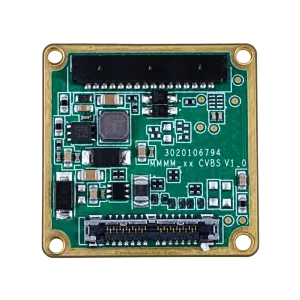
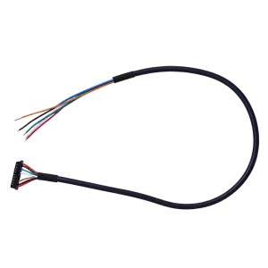
For the 9 mm sample: one AeroMini 640 camera module with 9 mm lens, one USB + CVBS + MIPI tailboard, and one USB cable requiring customer soldering. Accessories are itemized in the sample quotation.
What is included with the Type-C + CVBS sample kit?
For the 9 mm sample: one AeroMini 640 camera module with 9 mm lens, one Type-C + CVBS tailboard, and one supplied wiring cable, and one USB-C data cable. Accessories are itemized in the sample quotation.
What is included when I select both tailboards and both cables?
For the 9 mm sample: one AeroMini 640 camera module with 9 mm lens, one USB + CVBS + MIPI tailboard, one Type-C + CVBS tailboard, one USB cable requiring customer soldering, and one supplied wiring cable, and one USB-C data cable. Accessories are itemized in the sample quotation.
Where can I find the connector and pinout?
See the expandable 26-pin MIPI / DVP connections section, the downloadable PDF, or CAMCUDA_AeroMini640_Integrated_EN.pdf in the technical documentation folder.
Are these pinouts suitable for the Type-C board?
The 16-pin and 26-pin diagrams below apply to the illustrated interface boards. Request the matched wiring guide for your Type-C board; do not substitute another board’s pinout.
Which power input should I use?
Use the approved input for your exact interface board. The illustrated POWER_IN1 and POWER_IN2 pins are 5 V inputs. The family-level 12 V specification does not make these pins 12 V compatible.
Which host platforms and MIPI output formats are supported?
For standard applications, we support Raspberry Pi 5, 64-bit ARM Linux systems and NVIDIA Jetson Nano. Confirm the interface board, firmware, video format and frame rate for your exact host and software environment. Send your processor or board model, supported video input formats, and Linux or JetPack version so we can check compatibility. Host-side reference: Raspberry Pi camera software documentation; it is not a product-specific compatibility guarantee.
Where can I get Linux drivers, examples and the SDK?
The USB-SDK.zip archive in the technical documentation folder contains Linux drivers, examples and the SDK.
Where are the control interface instructions and serial commands?
See AeroMini 640/CV Serial port in the technical documentation folder.
Is RAW or minimally processed video available?
The standard AeroMini 640 configuration does not meet this requirement. It requires a separate customization assessment, additional development costs, and a longer, less predictable development and testing cycle. Tell us whether this output is mandatory.
How can NUC/FFC behavior be adjusted?
NUC/FFC settings depend on the operating environment. Supported settings, such as automatic triggering behavior, can be adjusted through the PC software when needed.
Is a STEP file available for mechanical integration?
Yes. The STEP file in the technical documentation folder is for the 7 mm version; apart from the lens, everything else is identical. A 3D preview is also available on this product page.
How do I check the supplied firmware version?
We provide the latest stable firmware version number before shipment. The installed version can also be viewed through the PC software.
What are the main thermal imaging module applications?
AeroMini 640 is designed for compact OEM thermal imaging. Application areas include industrial monitoring, perimeter scanning, inspection robots, civil optoelectronic pods and UAV payloads. Select the camera version, lens and interface for the scene and host system. For UAV payloads, gimbals and civil optoelectronic pods, match the lens, interface board, power supply, mounting and software to your host. This is an integration module, not a complete drone camera or plug-and-play aircraft accessory.
Is AeroMini 640 suitable for electrical and power-system inspection?
The non-radiometric version provides thermal images for observing relative heat patterns in electrical and power-system inspection projects; it does not provide calibrated temperature measurements. If your workflow needs temperature readings, contact CAMCUDA about the 25 Hz radiometric version and its required configuration. That version is currently out of stock and available for supply enquiries only.
Can the module be used in fire-warning equipment or fire helmets?
Thermal observation for fire-warning equipment, rescue devices and helmet-mounted viewing systems is an OEM integration application. Contact CAMCUDA to review the intended environment, optics, enclosure and host requirements. The module alone is not a certified fire alarm or a complete protective helmet.
How does quantity pricing work?
Eligible non-radiometric configurations receive the displayed quantity discount. Quantities combine only when the camera version, lens, interface kit and factory frame rate match. Online orders are limited to 99 units per product; contact our team for 100 units or more.
How can I check shipping to my country?
Enter your destination country, delivery address and postal code in the Cart Summary before ordering. If no shipping option is shown, send us these details for a shipping quotation.
What is the estimated lead time?
For the AeroMini 640 with a 9 mm lens and USB + CVBS + MIPI, the estimated lead time is 14–20 working days for samples and orders up to 1,000 units. For 10,000 units, delivery can be as soon as one month, subject to the production schedule. For 50,000 units, we confirm the schedule against your required delivery plan.
Can production orders match my approved sample?
Yes. We can supply production orders with the same hardware and firmware configuration as the approved sample. Share your forecast early for larger orders so we can plan production.
Additional information
| Wersja kamery | Non-radiometric · 60 Hz default, optional 30 Hz factory configuration |
|---|---|
| Ogniskowa obiektywu | 4 mm, 7 mm, 9 mm, 13 mm, 18 mm, 25 mm, 35 mm, 50 mm |
| Pakiet interfejsów | Non-radiometric: USB + CVBS + MIPI; Type-C + CVBS; both boards; or CVBS only. |
Related products
-
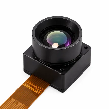
CAMCUDA TC160-NF 160 LWIR Thermal Camera Module
Evaluation samplesSample price on requestRequest sample pricing →Configuration & volume pricing100+ / 1000+ unitsEvery quotation states the configuration, quantity and delivery terms.Request volume pricing → -
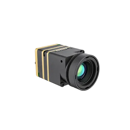
CAMCUDA SuperMini 640 / 640T Ultra-Light LWIR Thermal Camera Module
Evaluation samplesSample price on requestRequest sample pricing →Configuration & volume pricing100+ / 1000+ unitsEvery quotation states the configuration, quantity and delivery terms.Request volume pricing → -
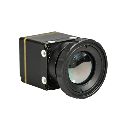
CAMCUDA FlexMini 640 OEM LWIR Thermal Camera Module
Price range: $423.10 through $629.00Lens options above 9.1 mm: Request a quoteOnline order1–99 units Price range: $423.10 through $629.00Configuration & volume pricing100+ / 1000+ unitsEvery quotation states the configuration, quantity and delivery terms.Request volume pricing →Choose configuration This product has multiple variants. The options may be chosen on the product page -
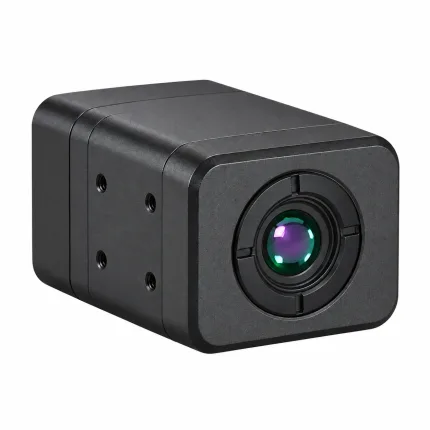
W640-TIF-K1 640×512 Uncooled VOx CVBS Thermal Imaging Module
Evaluation samplesSample price on requestRequest sample pricing →Configuration & volume pricing100+ / 1000+ unitsEvery quotation states the configuration, quantity and delivery terms.Request volume pricing →



