Thermal Imager Selection Guide: OEM Core Integration vs Handheld Devices
Thermal Imager Selection Guide: OEM Core Integration vs Handheld Devices
Selecting an industrial thermal imager requires a no-nonsense evaluation of electro-optical physics, digital signal architectures, and mechanical constraints. While entry-level consumer gadgets focus on crude qualitative heat mapping, mission-critical industrial inspection, aerospace payloads, machine vision, and defense surveillance systems demand high radiometric precision, razor-sharp spatial resolution, low Noise Equivalent Temperature Difference (NETD), and uncompromising SWaP-C (Size, Weight, Power, and Cost) efficiency. Engineering teams are continually confronted with a fundamental architectural crossroads: embed a modular OEM thermal core into custom gimbal or machine vision architectures, or roll out a turnkey, self-contained handheld observation instrument directly into the field.
This engineering selection guide delivers a deep dive into uncooled Long-Wave Infrared (LWIR) Vanadium Oxide (VOx) microbolometer technology. We break down the comparative advantages of high-definition modular sensor engines—such as the 1280×1024 SXGA HR-1280 core—alongside dedicated handheld observation platforms. By evaluating digital bus interfaces, optical Modulation Transfer Functions (MTF), Johnson’s Criteria for Target Acquisition (DRI modeling), power conversion topologies, and regulatory compliance protocols, this guide acts as a hands-on blueprint for optical engineers, systems integrators, and procurement leads looking to build bulletproof thermal platforms.
Table of Contents
- 👉 1. Core Physics & Sensor Architecture: Uncooled VOx LWIR Technology
- 👉 2. OEM Thermal Cores vs Handheld Instruments: Architectural & SWaP-C Tradeoffs
- 👉 3. Digital Video Interfaces, Control Protocols, and Host Bus Architectures
- 👉 4. Optical Selection, Lens Matching, and DRI Modeling
- 👉 5. Product Showcase & Engineering Specification Comparison
- 👉 6. OEM Sourcing, Compliance, and RFQ Engineering Checklist
- 👉 7. Frequently Asked Questions (FAQ)
1. Core Physics & Sensor Architecture: Uncooled VOx LWIR Technology
Industrial thermal imaging operates primarily within the Long-Wave Infrared (LWIR) atmospheric transmission window, spanning the electromagnetic spectrum from 8 µm to 14 µm. In this spectral band, terrestrial objects at ambient temperatures (around -40°C to +150°C) radiate peak thermal energy following Planck’s Radiation Law and the Stefan-Boltzmann Law. Because atmospheric absorption from water vapor, carbon dioxide, and ozone drops significantly in this 8–14 µm sweet spot, LWIR thermal sensors cut right through smoke, dust, light foliage, and pitch-black darkness without needing a shred of external illumination.
Here’s the deal with modern uncooled thermal sensors: they run on a microbolometer Focal Plane Array (FPA). Unlike cryogenically cooled photon detectors (such as InSb or MCT arrays) that require bulky stirling coolers running at 77 Kelvin, microbolometers are thermal detectors that operate reliably right around room temperature. Each individual pixel in the FPA consists of an absorbing membrane suspended over a silicon Readout Integrated Circuit (ROIC) by microscopic, thermally isolated support legs housed inside a high-vacuum metallic or ceramic package.
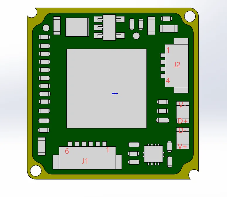
When incident infrared photons hit that absorber membrane, the absorbed radiation induces a tiny temperature rise (ΔT) across the pixel. This shift changes the electrical resistance of the thermistor thin film based on its Temperature Coefficient of Resistance (TCR):
ΔR = R0 · α · ΔT
where R0 is your baseline pixel resistance, α is the TCR, and ΔT is the thermal delta generated by incoming infrared flux. The underlying ROIC injects a precise bias current or voltage across each pixel to read out this resistance shift, turning that thermal gradient into an analog voltage that gets digitized by high-speed on-chip or off-chip Analog-to-Digital Converters (ADCs).
Vanadium Oxide (VOx) vs. Amorphous Silicon (a-Si)
In the shop, the choice of thin-film thermistor material dictates your signal-to-noise ratio (SNR), responsiveness, and long-term thermal stability. The two main materials competing on factory floors are Vanadium Oxide (VOx) and Amorphous Silicon (a-Si):
- ⚙️ Temperature Coefficient of Resistance (TCR): Vanadium Oxide regularly clocks a TCR between -2.0%/K and -3.0%/K at 295K, whereas Amorphous Silicon typically stalls around -1.5%/K to -2.0%/K. That higher TCR gives VOx sensors intrinsically greater responsivity and cleaner sensitivity to subtle thermal shifts.
- ⚙️ 1/f Flicker Noise Characteristics: VOx features a stable mixed-valence crystalline microstructure, yielding dramatically lower low-frequency 1/f noise than the disordered covalent networks in a-Si films. Lower 1/f noise means VOx FPAs can run much longer intervals between Non-Uniformity Correction (NUC) shutter clicks, eliminating annoying freeze-frames during dynamic tracking operations.
- ⚙️ Thermal Time Constant (τ): The thermal response time (τ = Cth / Gth, where Cth is pixel heat capacity and Gth is thermal conductance) of VOx microbolometers hovers tightly between 8 ms and 12 ms. This rapid thermal cycle allows full 50 Hz frame rates without the annoying motion ghosting, latency, or pixel smearing common in sluggish detector architectures.
Pixel Pitch Scaling: The 12 µm Architecture
The progression of thermal detector fabrication from legacy 25 µm and 17 µm nodes down to modern 12 µm pixel pitch structures has fundamentally changed electro-optical engineering. Shrinking the pixel pitch to 12 µm delivers massive operational wins:
- ✅ Opto-Mechanical Mass Reduction: Because the spatial footprint of the sensor die shrinks for any given resolution, the focal length needed to hit an equivalent Instantaneous Field of View (IFOV) is drastically shorter. That cuts the diameter and mass of expensive Germanium elements by up to 50%, immediately shaving critical ounces off drone and mobile payloads.
- ✅ Extreme SWaP-C Optimization: Smaller silicon dies allow ultra-compact packaging. High-resolution modules like the HR-1280 measure just 35 × 35 × 35 mm with a bare core weight of only 68 grams.
- ✅ High-Density Matrix Scaling: Wafer yields improve significantly while allowing high-definition native arrays—such as 1280×1024—to drop straight into mechanical form factors that used to be maxed out at standard VGA (640×512).
Noise Equivalent Temperature Difference (NETD) Physics
Noise Equivalent Temperature Difference (NETD) is the defining benchmark for any serious thermal imager. It quantifies the target temperature difference that produces a signal-to-noise ratio of exactly one (SNR = 1) at the sensor output. The formula breaks down as:
NETD = Vn / [ ( ΔVs / ΔT ) ] = 4 · F#2 · Vn / [ τopt · Apix · (ΔP / ΔT)λ1-λ2 · Rv ]
where Vn is total electrical noise voltage, F# is the optical f-number, τopt is lens transmission, Apix is the pixel area, and Rv is detector responsivity. NETD is rated in millikelvins (mK) at 25°C using an F#1.0 optic:
- ⚙️ NETD ≤ 50 mK: Industry entry baseline; acceptable for broad qualitative maintenance checks and basic elevated body temperature screenings.
- ⚙️ NETD ≤ 35 mK: The true industrial engineering benchmark (featured on the HR-1280 core), built for high-definition edge detection, automated machine vision, structural Non-Destructive Testing (NDT), and aerial surveillance.
- ⚙️ NETD ≤ 20 mK: Extreme high-sensitivity class (found in top-tier handheld observation instruments), built to pull micro-Kelvin thermal details out of flat, low-contrast scenes, heavy marine fog, light precipitation, and long-range tactical missions.
2. OEM Thermal Cores vs Handheld Instruments: Architectural & SWaP-C Tradeoffs
When selecting a thermal imager, engineering leads need to decide whether a modular OEM sensor core or a standalone handheld observation instrument matches their operational environment, software stack, and mechanical budget.
1. OEM Thermal Imaging Cores
Modular OEM thermal imaging cores, available through the thermal imaging cores catalog, are bare-metal electro-optical engines consisting of an FPA, ROIC, analog frontend, and an FPGA/DSP processing core. They are engineered from the ground up to sit directly inside larger host systems, like multi-axis EO/IR drone gimbals, factory automation enclosures, Autonomous Mobile Robots (AMR), and custom optical rigs.
The primary advantage of an OEM core comes down to pure Size, Weight, Power, and Cost (SWaP-C) efficiency. Stripped clean of external housings, displays, mechanical buttons, and batteries, an OEM engine like the HR-1280 weighs only 68 grams and sips power across a wide input rail (5–24V DC). Integrators get complete control over raw video pipelines, custom NUC calibration tables, unique color maps, bad pixel replacement (BPR), and edge AI inference models.
Keep in mind that OEM cores demand serious engineering commitment. Your team is fully responsible for conductive chassis heatsinking, interface carrier board routing, custom digital video deserialization, and writing rock-solid software drivers for command-and-control serial protocols.
2. Handheld Thermal Observation Instruments
Handheld thermal observation instruments take the opposite route: they are complete, turnkey electro-optical packages. They bundle the microbolometer sensor, image processing boards, Germanium optics, ocular display (high-resolution OLED or micro-LCD viewfinder), rechargeable Lithium-Ion power subsystem, and ergonomic tactical controls into a ruggedized, sealed chassis (typically IP66 or IP67).
Handheld units excel when you need immediate boots-on-the-ground capability. Search-and-rescue teams, industrial electrical inspectors, border units, and wildlife researchers can power them up and start working immediately without running code or designing PCBs. The onboard firmware handles image enhancement, digital zoom steps, on-screen display (OSD) menus, palette toggling (White Hot, Black Hot, Red Hot, Ironbow), and internal storage.
The engineering tradeoff is architectural rigidity: these devices have fixed enclosures, cannot be seamlessly embedded into tight drone payloads, sit in the ~550 gram weight class, and rarely expose raw 14-bit uncompressed sensor feeds.
3. Digital Video Interfaces, Control Protocols, and Host Bus Architectures
For integrators dropping an OEM thermal engine into an embedded setup, creating a stable, ultra-low-latency pipeline between the core and the host processor is job number one. For an exhaustive hardware selection breakdown, check out our infrared camera module OEM buying guide.
Digital Video Output Pipelines
Modern high-definition thermal engines deliver multiple digital output options to interface cleanly with diverse host computing stacks:
- ⚙️ BT.1120 Parallel Video: A 16-bit synchronous parallel digital video bus designed for uncompressed progressive HD streams. The HR-1280 pushes raw or processed 1280×1024 digital frames over BT.1120 at a full 50 Hz directly into FPGA fabric or high-speed SoC ports with zero pipeline latency.
- ⚙️ BT.656 Video: An 8-bit parallel digital bus with embedded SAV/EAV synchronization codes, well-suited for standard definition sensors (384×288 or 640×512) or legacy downsampled video streams.
- ⚙️ SDI (Serial Digital Interface): The broadcast-grade standard (HD-SDI) for transmitting uncompressed, zero-latency digital video over 75-ohm coaxial cable up to 100 meters. SDI is a workhorse in airborne Unmanned Aerial Vehicle (UAV) gimbals and pan-tilt-zoom (PTZ) surveillance turrets.
- ⚙️ CameraLink: A dedicated high-throughput LVDS protocol delivering raw 14-bit radiometric data streams straight to industrial frame grabbers, making it the top pick for metrology, machine vision, and automated factory lines.
- ⚙️ MIPI CSI-2 via Hardware Bridge: In modern embedded Linux architectures (NVIDIA Jetson, NXP i.MX8, Rockchip), engineers route parallel video streams (BT.1120) through bridge chips to output MIPI D-PHY lanes directly into the host processor’s hardware Image Signal Processor (ISP).
Serial Command & Control Pipelines
Programmatic control over the thermal engine relies on industrial-grade serial buses:
- ⚙️ RS-232: Asynchronous single-ended serial communication, perfect for board-to-board control over short trace runs.
- ⚙️ RS-422 / RS-485: Differential transmission standards delivering rock-solid common-mode noise rejection over long cable runs, making them vital for noisy industrial floors and slip-ring gimbal wiring harnesses.
- ⚙️ Command Set Capabilities: Host microcontrollers push byte-level hex commands over RS-232/RS-485/RS-422 to trigger NUC shutter cycles, tweak dynamic range algorithms (like Digital Detail Enhancement – DDE), swap palettes, manage digital zoom steps (1× to 8×), and pull raw telemetry metadata.
4. Optical Selection, Lens Matching, and DRI Modeling
Because standard optical glass (BK7, fused silica) acts like a brick wall to 8–14 µm LWIR light, a thermal imager requires specialized materials. Optical designers rely on high-purity single-crystal Germanium (Ge) or specialized Chalcogenide infrared glass formulations, coated with Anti-Reflective (AR) layers and rugged Diamond-Like Carbon (DLC) exterior coatings to survive abrasive environments.
Optical Throughput & F-Number Impact
Total radiant thermal energy hitting the microbolometer FPA is inversely proportional to the square of the optical F-number:
Radiant Flux ∝ 1 / (F#)2
Look at the math: an F#1.0 lens pulls in double the radiant thermal flux of an F#1.4 lens. Pairing your microbolometer with fast F#1.0 optics ensures the sensor extracts maximum thermal contrast with the lowest possible NETD noise floor.
Spatial Resolution and Field of View Equations
Matching your Germanium focal length to the sensor pixel dimensions dictates spatial sampling and field coverage. The math centers on two key formulas:
1. Instantaneous Field of View (IFOV): The angular field covered by a single detector pixel, measured in milliradians (mrad):
IFOV (mrad) = [ Pixel Pitch (µm) / Focal Length (mm) ]
Example: A 12 µm pixel pitch behind a 50 mm lens yields: IFOV = 12 / 50 = 0.24 mrad. At 1,000 meters, a single pixel covers exactly 24 cm × 24 cm of target area.
2. Horizontal Field of View (HFOV): The total horizontal angular spread of the scene:
HFOV = 2 · arctan [ (Nh · Pixel Pitch) / (2 · Focal Length) ]
where Nh is your horizontal pixel count (1280 for the HR-1280, or 640 for standard VGA cores).
Johnson’s Criteria: DRI Modeling for 12 µm Microbolometer Systems
Target acquisition ranges are modeled using Johnson’s Criteria, defining the minimum spatial line pairs needed across a target’s critical dimension for a 50% detection probability:
- ⚙️ Detection (1.5 line pairs / ~3 pixels): The operator spots an anomaly or object distinct from the background.
- ⚙️ Recognition (6.0 line pairs / ~12 pixels): The operator classifies the target class (e.g., distinguishing a truck from a tank, or a person from livestock).
- ⚙️ Identification (12.0 line pairs / ~24 pixels): The operator pinpoints specific features (e.g., identifying vehicle variants or spotting handheld gear).
When selecting optics for the HR-1280 (offering 9 mm, 13 mm, 19 mm, 25 mm, 35 mm, 50 mm, 75 mm, and 100 mm options), wide focal lengths (9–19 mm) deliver broad situational awareness for drone mapping and robotic navigation. Long telephoto optics (50–100 mm) compress the HFOV to resolve distant targets kilometers away.
5. Product Showcase & Engineering Specification Comparison
Here is the direct technical breakdown of our two primary platforms: the high-resolution HR-1280 OEM Thermal Imaging Module and the field-ready Handheld Infrared Thermal Observation Instrument.
HR-1280 1280×1024 Uncooled LWIR Thermal Imaging Module
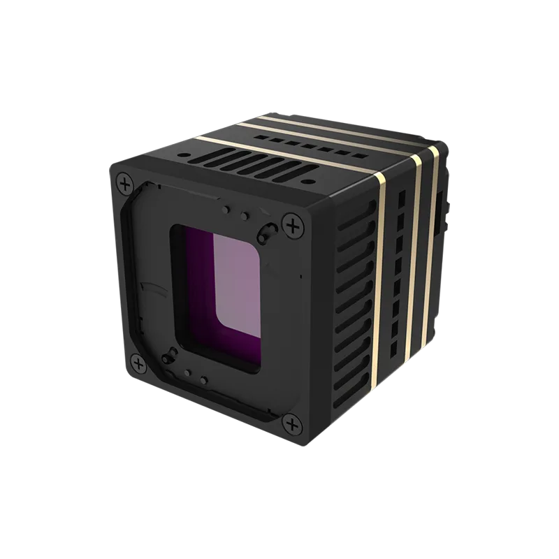
The HR-1280 is a high-definition 1280×1024 uncooled VOx LWIR thermal imaging engine built for aerospace engineers, defense system integrators, and industrial machine vision developers. Packing over 1.31 million active 12 µm thermal sensing pixels into an ultra-compact 35×35×35 mm footprint weighing only 68 grams (without lens), it provides high spatial resolution for drone gimbals, advanced robotics, and industrial process monitoring.
Engineered with a versatile hardware pipeline supporting BT.656, BT.1120, SDI, and CameraLink digital video buses alongside RS232, RS485, and RS422 serial interfaces, the HR-1280 simplifies system-level integration across heterogeneous processing platforms. Its wide-range 5–24V DC power rail ensures seamless compatibility with varied unregulated payload power buses.
| Parameter | Preserved Engineering Specification |
|---|---|
| Detector Type | Uncooled VOx (Vanadium Oxide) Microbolometer |
| Native Array Resolution | 1280 × 1024 pixels (SXGA Format) |
| Pixel Pitch | 12 µm |
| Spectral Response Band | 8 µm to 14 µm (Long-Wave Infrared) |
| Full Frame Rate | 50 Hz Real-Time |
| Thermal Sensitivity (NETD) | ≤ 35 mK @ 25°C, F#1.0 |
| Optical Lens Options | 9 / 13 / 19 / 25 / 35 / 50 / 75 / 100 mm focal lengths |
| Digital Video Output | BT656 / BT1120 / SDI / CameraLink (Note: CVBS not supported) |
| Communication Interfaces | RS232 / RS485 / RS422 Serial Command Protocols |
| Operating Voltage Rail | 5 V to 24 V DC Wide-Input Rail |
| Mechanical Dimensions | 35 × 35 × 35 mm (bare core without lens) |
| Physical Weight | 68 g (bare core without lens) |
| Regulatory Compliance | NDAA compliance statement available upon RFQ request |
Handheld Infrared Thermal Observation Instrument
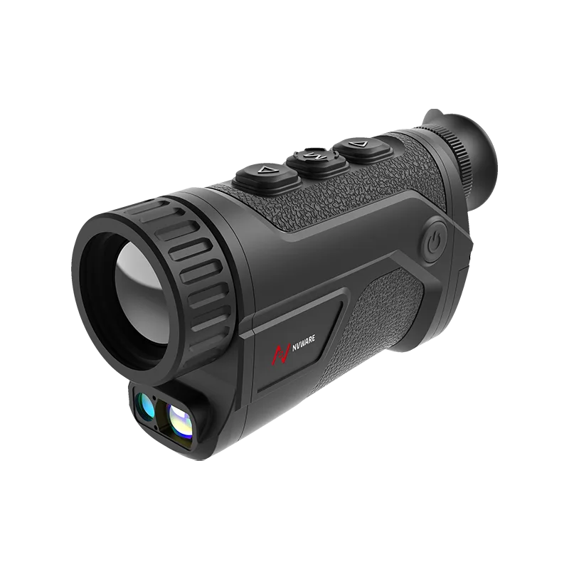
The Handheld Infrared Thermal Observation Instrument is an integrated, portable electro-optical field device engineered for mobile personnel requiring immediate thermal situational awareness. Tailored for border patrol, tactical search and rescue, perimeter monitoring, and electrical utility inspection, this instrument features dual configuration paths supporting either 384×288@12um or 640×512@12um VOx uncooled detector arrays.
Boasting a high thermal sensitivity of ≤ 20 mK (@25°C, F#1.0, 25Hz), this handheld instrument isolates critical thermal gradients in low-contrast conditions such as humid nights, fog, and light foliage. Packaged in a field-ready, ruggedized housing in the ~550g weight class, it features precision 25mm, 35mm, or 50mm F1.0 Germanium optics for flexible target identification ranges.
| Parameter | Preserved Engineering Specification |
|---|---|
| Sensor Core Platform | VOx Uncooled Sensor Platform |
| Spectral Response Range | 8 µm to 14 µm (LWIR Band) |
| Resolution Configuration Paths | Selectable: 384 × 288 @ 12 µm OR 640 × 512 @ 12 µm |
| Pixel Pitch | 12 µm |
| Frame Rate Refresh | 50 Hz Real-Time Readout |
| Thermal Sensitivity (NETD) | ≤ 20 mK @ 25°C, F#1.0, 25Hz |
| Standard Lens Options | 25 mm / 35 mm / 50 mm F1.0 Fast Optical Elements |
| Instrument Weight Class | Approx. 550 g class (complete mobile field assembly) |
| Operational Focus | Outdoor observation, search & rescue, patrol, mobile inspection |
| Regulatory Compliance | NDAA compliance statement available upon RFQ request |
6. OEM Sourcing, Compliance, and RFQ Engineering Checklist
Sourcing a high-grade thermal imager engine or instrument requires pinning down optical specs, electrical pinouts, and export rules before cutting purchase orders. To skip costly redesign cycles, run through our thermal camera suppliers OEM RFQ checklist prior to sign-off.
When drafting your technical RFQ submission, make sure every base is covered across these core areas:
1. Optical & Spatial Target Profiling
- ⚙️ Target Array Resolution: Lock in your required array class (SXGA 1280×1024 for high-definition surveillance, or 640×512 / 384×288 for tighter SWaP budgets).
- ⚙️ Focal Length and IFOV: Define target dimensions (e.g., 1.8m human or 2.3m vehicle) alongside needed DRI ranges in meters. Choose from 9 mm up to 100 mm optics.
- ⚙️ Athermalization & Environmental Coatings: Specify passive optical athermalization requirements (-40°C to +60°C) and Diamond-Like Carbon (DLC) hard exterior coatings for abrasive field conditions.
2. Electrical, Hardware Bus, and Signal Architecture
- ⚙️ Primary Digital Video Bus: Select your host interface: BT.1120 (progressive HD parallel), BT.656, SDI (broadcast coax), or CameraLink (raw 14-bit machine vision). Heads up: confirm analog CVBS is not needed, as modern modules like the HR-1280 focus on pure digital streams.
- ⚙️ Command & Telemetry Link: Match serial logic levels and physical transceiver chips (RS-232, RS-422, or differential RS-485).
- ⚙️ Power Rail Budget: Verify input voltage compatibility (the HR-1280 handles wide 5–24V DC rails; confirm transient suppression for battery spikes).
3. Mechanical Packaging, SWaP-C, and Thermal Management
- ⚙️ Payload Space Envelope: Confirm 3D envelope limits (e.g., HR-1280 bare dimensions of 35 × 35 × 35 mm, bare weight 68g).
- ⚙️ Thermal Conduction Path: Design solid conductive heatsinking paths into your chassis to keep the microbolometer substrate thermally stable during heavy workloads.
- ⚙️ Environmental Enclosure Rating: Differentiate between bare OEM engines slated for sealed gimbals versus self-contained, weather-sealed handheld units (~550g class).
4. Regulatory Compliance & Global Export Clearances
- ⚙️ NDAA Section 889 Compliance: Request formal NDAA compliance documentation to qualify for federally funded defense and aerospace contracts.
- ⚙️ Dual-Use Export Classification: Fast 50 Hz LWIR thermal devices are subject to international dual-use export controls. Declare destination countries, end-user profiles, and use cases right away in your initial RFQ.

7. Frequently Asked Questions (FAQ)
Why do low-cost consumer thermal imagers fail in professional industrial and aerospace inspection tasks?
When should an engineering team choose an OEM thermal imager module over a standalone handheld camera?
How does the NETD rating impact real-world target detection in low-contrast environments?
📚 References & Further Reading
- Industry Standard: MIPI Alliance D-PHY Physical Layer Specification for Mobile & Embedded Video
- Payload Engineering Standard: Wikipedia – Unmanned Aerial Vehicle Architecture & Payload Systems
- Core Sourcing Guide: Camcuda Modular Thermal Imaging Cores Catalog
- OEM Procurement Reference: Infrared Camera Module OEM Integration and Buying Guide
- Engineering RFQ Guide: Thermal Camera Suppliers OEM RFQ Checklist and Sourcing Protocol


