Cheap Thermal Camera Guide: Evaluating Resolution, Frame Rate & OEM Value
If you’re an embedded hardware designer, robotics engineer, or systems architect hunting for a cheap thermal camera, your objective is straightforward: get reliable long-wave infrared (LWIR) vision into your build without spending aerospace-level money. But look at the market today, and you’ll find it split straight down the middle. On one side, you have sub-$300 smartphone dongles, hobby breakout boards, and cheap handhelds that use software trickery to cover up tiny, noisy microbolometers. On the other side, you have industrial-grade OEM Vanadium Oxide (VOx) thermal camera cores designed around raw physics, native resolution, high frame rates, and deterministic hardware interfaces. Picking consumer hardware for an industrial deployment might save a few bucks upfront, but it almost always leads to spatial blindness, severe thermal drift, lagging 9 Hz video feeds, and fragile drivers that crash under 24/7 workloads.
Here’s the deal: real cost-efficiency in thermal vision isn’t just the unit price on the invoice. It’s the performance-per-dollar over the lifetime of your product. Key hardware parameters—like thermal sensitivity (≤30 mK NETD), native spatial resolution (such as 640 x 512 focal-plane arrays), solid 50 Hz frame rates, and reliable low-level interfaces (MIPI D-PHY, USB UVC, and CVBS)—dictate whether your machine vision algorithm gets actionable data or useless blur. By running the numbers on optical transmission, bill-of-materials (BOM) trade-offs, thermal dissipation, and edge processing, engineering teams can pick high-ROI cores—like the Camcuda MD-64CA core and the TM02-SOLO T AI tracking module—that cut integration headaches while meeting tough operational specs.
Table of Contents
- 👉 1. Deconstructing the “Cheap Thermal Camera” Market: Consumer vs. OEM Cores
- 👉 2. Critical Selection Metrics: Resolution, Pixel Pitch, NETD, and Frame Rate
- 👉 3. Optics Selection & Embedded Hardware Interfaces (MIPI, USB UVC, CVBS)
- 👉 4. High-Value OEM Thermal Solutions: Detailed Specification Breakdown
- 👉 5. Advanced Integration: Dual-Spectrum Payloads & Edge AI Target Tracking
- 👉 6. OEM Engineering Checklist: Mitigating Thermal Drift, Power Ripple, and Latency
- 👉 7. Deep-Dive Frequently Asked Questions (FAQ)
1. Deconstructing the “Cheap Thermal Camera” Market: Consumer vs. OEM Cores
The Pitfalls of Sub-$300 Consumer Dongles and Handhelds
When searching for a budget thermal module or cheap thermal camera, you’ll run into dozens of smartphone add-ons, DIY breakout boards, and cheap handhelds priced between $150 and $400. While these gadgets are fine for finding a draft in your living room or checking a radiator, putting them into an industrial automation rig, commercial drone, or automated inspection cell is asking for trouble.
The main issue comes down to the physical detector array. Most sub-$300 thermal units use tiny focal-plane arrays (FPAs) of 80 x 60 (4,800 pixels) or 160 x 120 (19,200 pixels), often built on lower-grade Amorphous Silicon (α-Si). In a real-world scenario—like inspecting a dense printed circuit board (PCB) or running autonomous navigation—160 x 120 just doesn’t provide enough pixels. Surface-mount passives (0402 or 0603 packages), voltage regulators, and power MOSFETs get averaged together into single smeared pixels. A localized 95°C hot spot on an inductor gets averaged with the cool ground plane around it, reporting a safe-looking 45°C. That’s a major blind spot.
To mask these hardware limits, consumer dongles lean heavily on software tricks: digital edge enhancement, bicubic smoothing, and multi-spectral edge blending (slapping high-pass outlines from a visible sensor over the thermal feed). It looks decent on a 6-inch phone display, but it’s a visual illusion. Underneath, the raw radiometric data matrix is low-resolution, noisy, and practically useless for machine vision, automated safety shutoffs, or deterministic temperature analysis.
Then there’s the supply chain reality. Consumer devices have rapid obsolescence cycles, undocumented PCB revisions, and die-stepping changes every few quarters. Their software support often stops at proprietary, sandboxed Android or iOS apps with no root access or low-level API hooks. Trying to build an industrial product around a consumer dongle means fighting driver breakages across Linux kernel patches, poor vibration tolerance, and housings that can’t handle thermal cycling on the factory floor.
The True Definition of Low-Cost in OEM Integration
In embedded hardware development, “low cost” shouldn’t mean a cheap purchase price that blows up your development budget down the line. It means optimizing the Total Cost of Ownership (TCO) across design, testing, mass production, and field maintenance. A high-ROI uncooled thermal core provides clean, direct access to raw digital streaming frames, predictable calibration, standard hardware buses, and guaranteed long-term component availability.
Uncooled Vanadium Oxide (VOx) microbolometers are the gold standard for price-to-performance in the LWIR spectrum. Compared to older Amorphous Silicon (α-Si), VOx offers a higher temperature coefficient of resistance (TCR) and significantly lower 1/f noise. That allows VOx cores to hit noise equivalent temperature differences (NETD) of ≤30 mK to ≤40 mK, retaining high sensitivity even on tight 12 μm pixel pitches. For an in-depth breakdown on choosing the right platform, check out our thermal camera core selection and integration checklist.
When you design around a dedicated OEM core instead of trying to hack a consumer dongle, you save hundreds of engineering hours on driver wrappers, mechanical adapters, and optical re-calibrations. Standard mounting bosses, defined thermal dissipation interfaces, factory-aligned lenses, and standard hardware buses mean the sensor drops into your host architecture cleanly on the first spin of the board.
2. Critical Selection Metrics: Resolution, Pixel Pitch, NETD, and Frame Rate
Native Spatial Resolution (640 x 512 vs. Entry-Level Arrays)
Spatial resolution in LWIR imaging comes down to the physical microbolometer pixel count. In visible cameras, multi-megapixel silicon sensors are cheap to stamp out. In thermal imaging, building microbolometers requires specialized MEMS vacuum encapsulation and expensive Germanium optics. Stepping up in array size directly impacts your budget, but the engineering payoff is massive.
Let’s look at the actual pixel counts:
- ⚙️ 160 x 120 Array: 19,200 active pixels (Entry-level consumer territory)
- ⚙️ 256 x 192 Array: 49,152 active pixels (Basic utility inspection)
- ⚙️ 384 x 288 Array: 110,592 active pixels (Mid-range industrial monitoring)
- ⚙️ 640 x 512 Array: 327,680 active pixels (Professional OEM benchmark)
A native 640 x 512 focal plane array gives you over 17 times the spatial data of a 160 x 120 sensor. Under the Johnson Criteria for target acquisition, system performance for Detection, Recognition, and Identification (DRI) scales directly with line pairs resolved across a target. For a UAV payload or automated ground vehicle, a 640 x 512 core detects targets at more than triple the distance of an entry-level array using the same field-of-view (FOV) lens.
The move to a 12 μm pixel pitch is what makes modern high-resolution thermal imaging affordable. Older cores used 17 μm or 25 μm pitches, which required much larger focal planes for the same pixel count. Larger focal planes demand physically larger, heavier, and far more expensive Germanium optical elements to cover the image circle. With a 12 μm 640 x 512 array, the image circle stays small, allowing lightweight, compact optics with minimal Germanium mass—slashing optical BOM costs while preserving crisp spatial sampling.
Noise Equivalent Temperature Difference (NETD) and Thermal Sensitivity
Noise Equivalent Temperature Difference (NETD) measures the sensitivity of an infrared sensor. Expressed in millikelvins (mK), it represents the temperature difference needed to produce an electrical signal equal to the sensor’s internal readout noise (SNR = 1). Lower numbers mean a cleaner, more sensitive thermal capture.
Budget consumer thermal cameras often have NETD ratings between 70 mK and 100 mK (0.07°C to 0.10°C) at F1.0. In low-contrast scenes—like overcast skies, uniform concrete surfaces, marine environments, or insulated electrical enclosures—these sensors produce washed-out, noisy images full of static. High-performance OEM cores like the MD-64CA deliver an NETD of ≤30 mK (@ F1.0). That ≤30 mK sensitivity allows the detector to resolve temperature differences as fine as 0.03°C, pinpointing subtle insulation bypasses, tiny moisture ingress routes, or early-stage junction overheating on complex circuit boards long before they fail.
Temporal Resolution: Why 50 Hz Frame Rates Matter
Temporal performance is measured in frames per second (Hertz). Most entry-level consumer cameras and unmonitored modules are capped at 9 Hz (or 8.7 Hz). This limit is primarily due to international export control rules (like the Wassenaar Arrangement and US EAR frameworks), which treat high-rate (≥30 Hz) thermal cameras as dual-use goods requiring export clearance.
A 9 Hz frame rate might work for inspecting a stationary circuit breaker or finding attic air leaks, but it falls apart in dynamic environments. At 9 Hz, the frame updates every 111 milliseconds. In machine vision inspection lines, robotic arms, or UAV flight payloads, 111 ms creates heavy motion blur, image tearing, and disorienting lag whenever the camera pans.
A native 50 Hz frame rate refreshes the full array every 20 milliseconds. That speed is essential for:
- ✅ Robotics and Obstacle Avoidance: Providing smooth, low-latency visual odometry in pitch-black environments without motion smear.
- ✅ UAV Gimbal Tracking: Keeping tracking loops locked onto moving ground vehicles traveling at speeds over 100 km/h.
- ✅ Edge AI Inference: Feeding steady, blur-free frame streams into convolutional neural networks (CNNs) to maintain target tracking through rapid movements.
3. Optics Selection & Embedded Hardware Interfaces (MIPI, USB UVC, CVBS)
Germanium Optics and Field of View (FOV) Geometry
Standard optical glass (like BK7 or fused silica) is opaque to long-wave infrared light in the 8 to 14 μm band. Because of this, thermal cameras require specialized optics made from monocrystalline Germanium (Ge), Chalcogenide glass, or Zinc Selenide (ZnSe). Germanium has a high refractive index (~4.0) and excellent LWIR transmission, but raw material costs make optics a significant part of the overall module price.
High-grade optical manufacturing from specialists like Ophir IR Optics uses anti-reflective (AR) and Diamond-Like Carbon (DLC) coatings to protect external lens surfaces from moisture and abrasion while maximizing photon transmission to the microbolometer.
Selecting the right focal length upfront is essential. OEM modules are typically factory-assembled with athermalized, fixed-focus lens barrels to maintain optical alignment and environmental sealing across wide temperature swings. Here is how focal lengths, apertures, and fields of view pair up on a 12 μm 640 x 512 uncooled VOx sensor:
| Focal Length | Aperture (F-number) | Horizontal FOV (H-FOV) | Vertical FOV (V-FOV) | Primary Application Domain |
|---|---|---|---|---|
| 4.9 mm | F1.0 | 76.2° | 64.2° | Wide situational awareness, indoor mobile robotics, close-up electronics test benches |
| 9.1 mm | F1.0 | 45.8° | 37.3° | Standard aerial drone payloads, industrial robotics, general security sweeps |
| 13.0 mm | F1.0 | 33.0° | 26.6° | Perimeter security, power utility pole inspection, search and rescue operations |
| 19.0 mm | F1.0 | 22.9° | 18.4° | Long-range vehicle monitoring, elevated facility security, wildfire hot-spot tracking |
| 35.0 mm | F1.0 | 12.5° | 10.0° | Extended standoff target identification, border surveillance, defense telemetry |
Interfacing with Host Compute Platforms
A common headache when integrating low-cost thermal hardware is the interface. Consumer cameras often rely on high-latency USB bridge chips or proprietary wireless links with unpredictable packet jitter. Industrial OEM cores provide low-level, deterministic hardware interfaces designed for embedded platforms:
- ⚙️ MIPI CSI-2 / D-PHY: For direct hardware connections to SoCs like NVIDIA Jetson, Rockchip RK3588, or Raspberry Pi Compute Modules, the MIPI D-PHY physical layer moves uncompressed pixel streams directly into the host Image Signal Processor (ISP). This bypasses the USB software stack, delivering sub-10 ms glass-to-glass latency for real-time control loops.
- ⚙️ USB Video Class (USB UVC): The preferred choice for quick prototyping on Linux, Windows, and ROS (Robot Operating System). A standard UVC thermal core functions as a driverless capture device, streaming 14-bit raw radiometric matrices or 8-bit YUV/RGB video directly to OpenCV pipelines.
- ⚙️ Analog Composite Video (CVBS): Ideal for long-range analog FPV video transmitters, low-cost video switchers, and legacy field displays. For complete details on building analog pipelines, check our CVBS thermal camera module analog video guide.
4. High-Value OEM Thermal Solutions: Detailed Specification Breakdown
To see how modern uncooled microbolometer design brings 640 x 512 thermal imaging into reachable price brackets, let’s look at two purpose-built OEM options: the standalone MD-64CA Core and the fully integrated TM02-SOLO T Dual-Spectrum AI Tracking Module.
MD-64CA: 640 x 512 Uncooled VOx Thermal Imaging Camera Module
The MD-64CA is an ultra-lightweight, compact LWIR core built for equipment builders, industrial diagnostic tools, security payloads, and drone gimbals. It pairs a native 640 x 512 VOx focal-plane array with a 12 μm pixel pitch, pushing a solid 50 Hz frame rate with high thermal sensitivity (≤30 mK NETD).
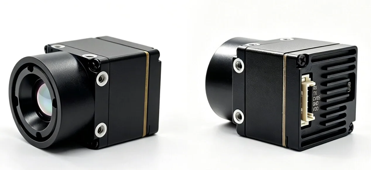
Drawing under 0.7 Watts across a wide 5 to 24 V DC input and weighing just 23.1 grams, the MD-64CA fits tight Size, Weight, and Power (SWaP) budgets. The core supports CVBS, USB UVC, and MIPI outputs, and comes factory-fitted with your choice of five F1.0 Germanium lenses ranging from 4.9 mm to 35 mm.
| Parameter | Specification Details |
|---|---|
| Detector Type | Uncooled VOx Focal-Plane Array |
| Array Resolution | 640 x 512 pixels |
| Pixel Pitch | 12 μm |
| Spectral Band | 8 to 14 μm (LWIR) |
| Thermal Sensitivity (NETD) | ≤30 mK (@ F1.0, 25°C) |
| Frame Refresh Rate | 50 Hz |
| Lens Options (F1.0) | 4.9 mm (76.2°x64.2°), 9.1 mm (45.8°x37.3°), 13 mm (33.0°x26.6°), 19 mm (22.9°x18.4°), 35 mm (12.5°x10.0°) |
| Video Interface Modes | CVBS (Analog), USB UVC (Digital Driverless), MIPI CSI-2 |
| Input Voltage & Power | 5–24 V DC; Power Consumption <0.7 W |
| Operating Temperature | -20°C to +60°C |
| Weight | 23.1 g (without external enclosure) |
Supply Boundary Note: The MD-64CA package includes the core module and factory-configured lens/interface. Custom mating cables, custom enclosures, host processors, and high-level software stacks are defined during the standard engineering RFQ process.
TM02-SOLO T: 6 TOPS UAV AI Tracking Module with 640 Thermal Camera
The TM02-SOLO T combines an electro-optical (EO) visible camera, an uncooled 640 x 512 VOx thermal sensor, and an onboard 6 TOPS neural processing unit (NPU) into a single 45 x 45 x 26 mm block. Designed for UAV builders and autonomous robotics developers, it handles real-time edge AI target tracking in daylight, low light, and total darkness without relying on a laggy ground station connection.
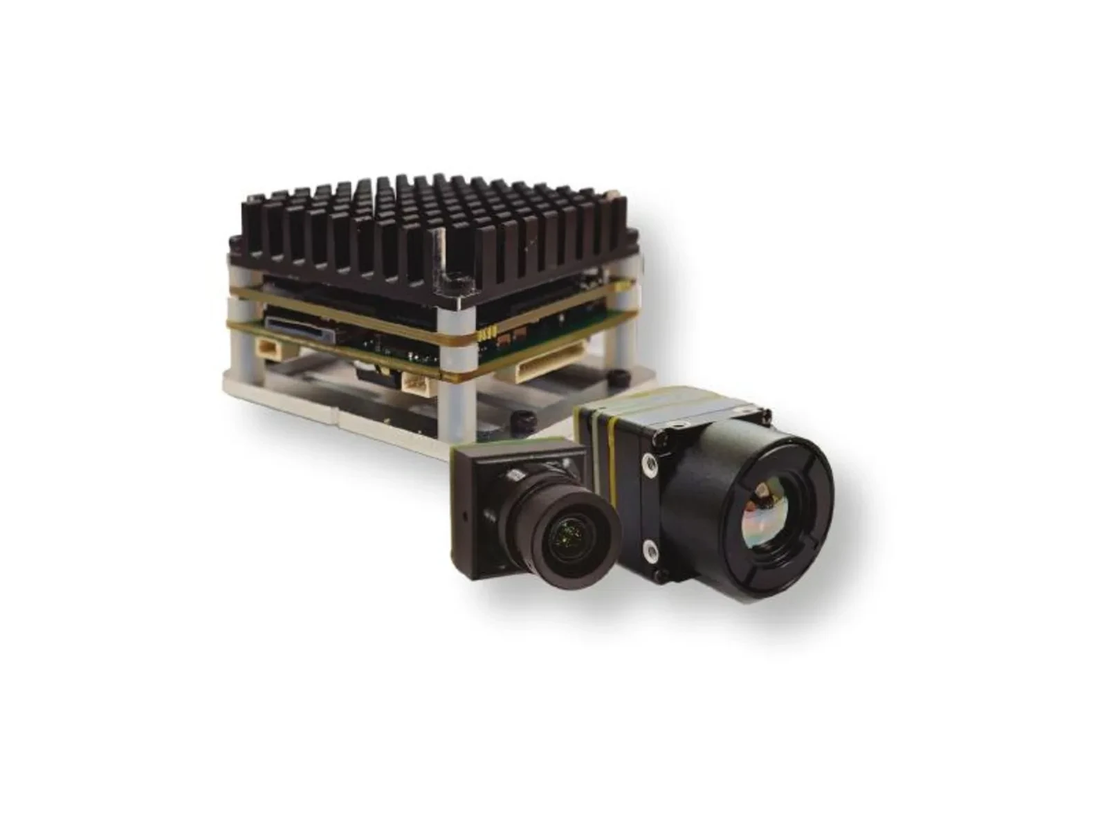
Its dual-spectrum setup pairs a 1080p visible camera running at 120 Hz (with 0.001 lux low-light sensitivity) alongside a 50 Hz 640 x 512 LWIR thermal channel. The onboard NPU tracks up to 120 targets simultaneously, picks out vehicles at 400 meters, detects people at 170 meters, and handles target speeds up to 450 km/h with an internal inference latency of roughly 8 ms.
| Subsystem | Technical Parameters & Capabilities |
|---|---|
| Edge AI Compute Engine | 6 TOPS Neural Processing Unit (NPU); Arm Cortex-A76 (2.4 GHz) + Cortex-A55 (1.8 GHz) |
| Tracking Capabilities | Person (170 m) and Vehicle (400 m); Min target size: 10×10 px; Speeds up to 450 km/h; Up to 120 concurrent tracks |
| Tracking Modes | Reticle locking, close-to-lock, route pre-map, lost-target recall, Picture-in-Picture (PIP) |
| Visible (EO) Optical Channel | 1/1.8″ Sensor, 8.45 mm lens (FOV: D 66.3° / H 57.1° / V 30.4°), 1080p @ 120 Hz, 0.001 lux min illumination |
| Thermal (IR) Channel | Uncooled VOx, 12 μm pitch, 640 x 512 @ 50 Hz, 9.1 mm lens (FOV: D 61.8° / H 47.7° / V 38.2°), 8–14 μm band |
| Flight Controller Interfaces | CRSF protocol support; native integration with BetaFlight and ArduPilot platforms |
| Power & Dimensions | Regulated 9–16 V DC input; Board dimensions: 45 x 45 x 26 mm (Mounting: 42.5 x 42.5 mm) |
Application Boundary Note: The TM02-SOLO T is tuned for real-time target tracking, visual odometry, and automated object recognition. It is not designed for calibrated radiometric temperature measurement.
5. Advanced Integration: Dual-Spectrum Payloads & Edge AI Target Tracking
Resolving Spatial Limitations via Dual-Spectrum Fusion
A standalone thermal camera gives you high contrast on heat sources, but it misses fine surface textures, color cues, and sharp optical depth. On the flip side, visible-light sensors struggle in dense fog, heavy shadows, smoke, or total darkness. Combining both into a single dual-spectrum setup solves the weaknesses of each spectrum.
In a dual-spectrum system like the TM02-SOLO T, the 1080p visible sensor runs at 120 Hz, capturing high-speed optical detail down to 0.001 lux. When ambient lighting disappears, or when targets blend into natural foliage, the 50 Hz 640 x 512 thermal channel exposes the target’s heat signature. By feeding both into Picture-in-Picture (PIP) displays or alpha-blended fusion pipelines, your navigation system gets high-frequency visual edges and clear thermal signatures at the same time.
Onboard Edge Compute with the TM02-SOLO T Platform
Typical drone setups send raw video back to a ground control station (GCS) over an RF link, where a laptop runs object detection. In real field conditions, this architecture introduces major weak points: compression artifacts degrade target recognition, transmission lag (often 150 to 300 ms) causes tracking overshoots, and simple RF interference can break the connection entirely.
By putting a dedicated 6 TOPS NPU and a dual-core Arm Cortex-A76 / Cortex-A55 processor right on the camera payload, the TM02-SOLO T runs neural inference at the edge. The system handles bounding-box calculations, feature tracking, and multi-object centroid math onboard with an internal latency of only 8 milliseconds. Target tracking coordinates convert directly into CRSF telemetry commands sent over UART to ArduPilot or BetaFlight flight controllers, keeping autonomous vehicle tracking active even through total RF telemetry dropouts.
For engineering teams working on multi-rotor, VTOL, or fixed-wing platforms, integrating gimbal payloads means balancing mass, balance point, and aerodynamic drag. To explore complete stabilized aerial payloads, check out our full drone camera ecosystem.
6. OEM Engineering Checklist: Mitigating Thermal Drift, Power Ripple, and Latency
When integrating an uncooled VOx thermal core into a production product, watch out for these three hardware engineering pitfalls:
1. Electrical and Power Supply Hygiene
Uncooled microbolometers are sensitive to noisy power rails. Switching noise or voltage ripple on the DC lines feeds right into the readout integrated circuit (ROIC), causing horizontal banding, vertical stripes, or frame noise.
- ⚙️ Keep Ripple Low: Ensure peak-to-peak power ripple is strictly under 30 mV on core supply lines. Place dedicated low-dropout (LDO) linear regulators downstream of your main switching buck converters to isolate the thermal sensor from motor surges or high-draw compute boards.
- ⚙️ Handle Inrush Current: While the steady-state draw on modules like the MD-64CA is minimal (<0.7 W), microbolometer bias calibration and onboard ISP boot cycles create momentary inrush spikes. Put low-ESR ceramic bypass capacitors close to the module connector pins.
- ⚙️ Shielding and Ground Planes: Route high-speed differential pairs (like MIPI D-PHY) over solid ground reference planes. Shield your flex cables to keep motor ESC noise or RF transmitters from bleeding into analog CVBS lines.
2. Thermal Conduction and Enclosure Design
Uncooled VOx microbolometers rely on internal mechanical shutters or shutterless software algorithms for Non-Uniformity Correction (NUC). NUC recalibrates the response of every pixel as the camera housing warms up or cools down. Poor mechanical enclosure design makes this much harder than it needs to be.
- ⚠️ Avoid Asymmetric Heating: Never mount the thermal core directly against high-heat components (like CPU heatsinks, motor drivers, or power stages) without thermal isolation. Uneven heating across the camera frame creates severe spatial thermal gradients, leading to vignetting and image drift.
- ✅ Provide Solid Conduction Paths: Build a clean, conductive metal heat path from the camera core housing directly to your outer system chassis. In sealed IP-rated housings, make sure internal temperatures don’t exceed the +60°C maximum rating.
- ⚙️ Use Proper Window Materials: If you enclose the camera behind a protective glass window, remember that standard glass, quartz, and acrylic block LWIR radiation completely. Use an anti-reflective coated Germanium (Ge) or Zinc Selenide (ZnSe) flat window, and calibrate your radiometric profiles to account for the 2% to 8% optical transmission loss.
3. Firmware, Interface, and Mechanical Verification
Before sending your carrier board to fabrication or cutting CNC aluminum enclosures, run through this final checklist:
- ⚙️ Verify Mechanical Clearances: Double-check the mounting hole spacing (such as the 42.5 x 42.5 mm pattern on the TM02-SOLO T), connector orientation, Germanium lens protrusion, and optical axis alignment relative to your enclosure datum.
- ⚙️ Confirm Output Formats: Decide whether your host OS pipeline expects raw MIPI CSI-2, driverless USB UVC (with 14-bit data streaming enabled), or analog CVBS. Confirm that connector part numbers and pinouts match your wiring harness.
- ⚙️ Clarify Measurement Needs: Determine whether your application requires absolute radiometric temperature measurement (calibrated temperature values per pixel) or qualitative thermal imaging. If you need NIST-traceable absolute surface temperatures, ensure calibrated firmware tables are specified before production orders are placed.
7. Deep-Dive Frequently Asked Questions (FAQ)
Are ultra-cheap thermal cameras under $300 actually worth it for technical inspection and prototyping?
Why do cheap thermal cameras lag, and when is a 50 Hz frame rate necessary?
What hidden integration costs exist when choosing a cheap consumer thermal camera over an OEM module?
What is the difference between thermal imaging and calibrated radiometric temperature measurement?
📚 References & Further Reading
- ⚙️ Industry Standard: MIPI D-PHY Physical Layer Specification
- ⚙️ Optical Physics Reference: Ophir IR Optics Engineering Resources
- ⚙️ Related Integration Guide: Thermal Camera Core Selection & Integration Checklist
- ⚙️ Analog Telemetry Integration: CVBS Thermal Camera Module Analog Video Integration Guide
- ⚙️ Aerial Payloads: Industrial Drone Camera & Gimbal Payload Solutions