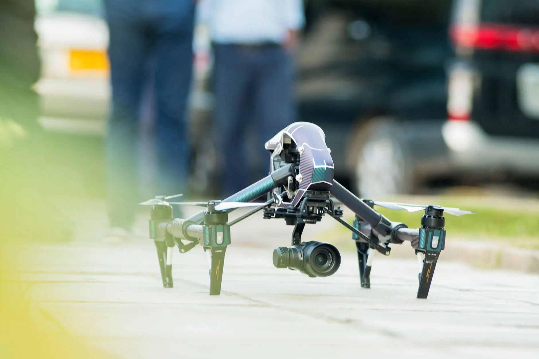
Drone with Thermal Camera: OEM Payload Integration & Selection Guide
Drone with Thermal Camera: OEM Payload Integration & Selection Guide
Unmanned aerial vehicles (UAVs) carrying long-wave infrared (LWIR) payloads have moved way past niche defense platforms. Today, they are standard gear for utility-scale solar audits, high-voltage line inspections, structural envelope scans, search and rescue (SAR), and perimeter security. But here’s the deal: building a rock-solid drone with thermal camera payload means wrestling with brutal Size, Weight, Power, and Cost (SWaP-C) trade-offs while trying to keep radiometric precision, clean optical resolving power, and low-latency digital signal pipelines intact. Off-the-shelf enterprise drones look convenient until you run straight into closed communications stacks, proprietary video streaming, fixed lenses, and punishing maintenance contracts that lock down your system architecture.
If you’re an aerospace robotics engineer, payload integrator, or OEM architect, building a modular or custom aerial thermal gimbal gives you complete control over your hardware and software stack. By wiring bare-module LWIR sensor cores straight into custom carrier boards, companion System-on-Chips (SoCs), and edge compute modules, you get true per-pixel radiometric telemetry, rock-solid multi-spectrum sensor fusion, and zero-latency flight control loops. This engineering guide breaks down the physical, electrical, and computational nuts and bolts of UAV thermal payload development—from microbolometer physics and optical selection to mechanical vibration isolation, bus topologies, and edge AI deployment.
Table of Contents
- 👉 1. Fundamental Physics: LWIR Sensing & Airborne Thermal Signatures
- 👉 2. SWaP-C Architecture for Drone Thermal Payloads
- 👉 3. Payload Integration: Optics, Gimbals, and Interfaces
- 👉 4. Edge Compute, Telemetry, and Radiometric Processing Pipelines
- 👉 5. Application Matrix: Selecting Resolution, Frame Rate & Lens Profiles
- 👉 6. OEM Component & Observer Comparison Table
- 👉 7. Detailed Hardware Breakdown: Embedded Sensors vs. Field Observers
- 👉 8. Step-by-Step OEM Integration & RFQ Checklist
- 👉 9. Frequently Asked Questions (Deep-Dive Engineering FAQ)
1. Fundamental Physics: LWIR Sensing & Airborne Thermal Signatures
Thermal payloads operate by picking up the electromagnetic radiation emitted by any matter sitting above absolute zero (0 Kelvin / -273.15°C). The math runs on Planck’s Law and the Stefan-Boltzmann Law, which proves that total radiant exitance from a blackbody surface climbs with the fourth power of its absolute thermodynamic temperature:
j* = ε · σ · T⁴
Here, ε is surface emissivity (from near 0.0 on polished bare copper to ~0.98 on water and vegetation), σ is the Stefan-Boltzmann constant (5.670374419 × 10⁻⁸ W·m⁻²·K⁻⁴), and T is the surface temperature in Kelvin. Airborne thermography lives in the Long-Wave Infrared (LWIR) atmospheric transmission window spanning 8 µm to 14 µm. This band cuts right between the heavy atmospheric absorption spikes of ozone, CO₂, and ambient humidity while capturing peak blackbody emissions for real-world targets across standard operating temperatures (-40°C to +150°C).
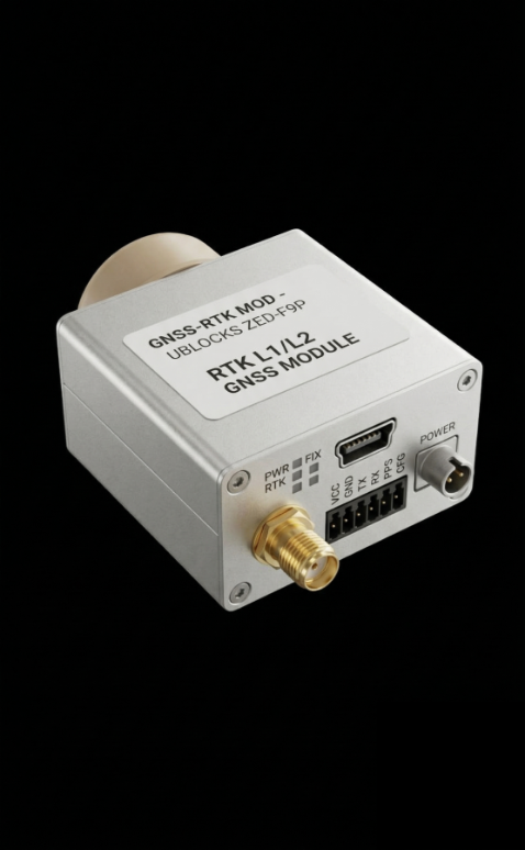
The heart of an airborne thermal payload is the uncooled microbolometer focal plane array (FPA). These are micro-electro-mechanical systems (MEMS) made of microscopic detector pixels suspended over a silicon read-out integrated circuit (ROIC) on microscopic thermal isolation legs. When LWIR photons hit the pixel active area, the absorbed energy changes the material’s electrical resistance. The ROIC samples this resistance shift across every single pixel on every frame cycle.
In the shop, you will almost always choose between two core materials: Vanadium Oxide (VOx) and Amorphous Silicon (α-Si). For aerial robotic payloads, VOx wins out almost every time:
- ✅ Higher Temperature Coefficient of Resistance (TCR): VOx runs a TCR between -2% and -3% per Kelvin, delivering cleaner signal-to-noise ratios (SNR) and better sensitivity than α-Si.
- ✅ Lower Noise Equivalent Temperature Difference (NETD): VOx detector arrays regularly hit sub-40 mK to 50 mK sensitivity with f/1.0 optics, letting your software pick up temperature deltas under 0.04°C.
- ✅ Fast Thermal Time Constants: Response times of 8 ms to 12 ms let the substrate track rapid thermal shifts, cutting out motion blur and smearing when the drone snaps into quick yaw or pitch maneuvers.
When you take these sensors airborne, slant-path atmospheric transmission losses become a major factor. The drone pushes a dynamic column of air between the target and your Germanium lens. Ambient moisture and air molecules absorb and re-emit LWIR photons, attenuating the true target signature. If you want absolute temperature numbers instead of just pretty pictures, your flight controller must feed live barometric altitude, outside air temperature, and relative humidity into the radiometric engine to solve the radiative transfer equation:
W_sensor = ε · τ_atm · W_obj + (1 – ε) · τ_atm · W_refl + (1 – τ_atm) · W_atm
Where W_sensor is the total radiance hitting the detector, τ_atm is the slant-path atmospheric transmission factor, W_obj is true object radiance, W_refl is reflected ambient background radiance, and W_atm is the self-emission of the air column. Miss these compensations, and your temperature calculations will drift wildly as the drone climbs or descends.
2. SWaP-C Architecture for Drone Thermal Payloads
Mounting a thermal payload onto a multirotor, fixed-wing, or VTOL frame requires balancing Size, Weight, Power, and Cost (SWaP-C). The physical mass and layout of your camera pod dictate your center of gravity (CoG), motor stability margins, aerodynamic drag, and flight time.
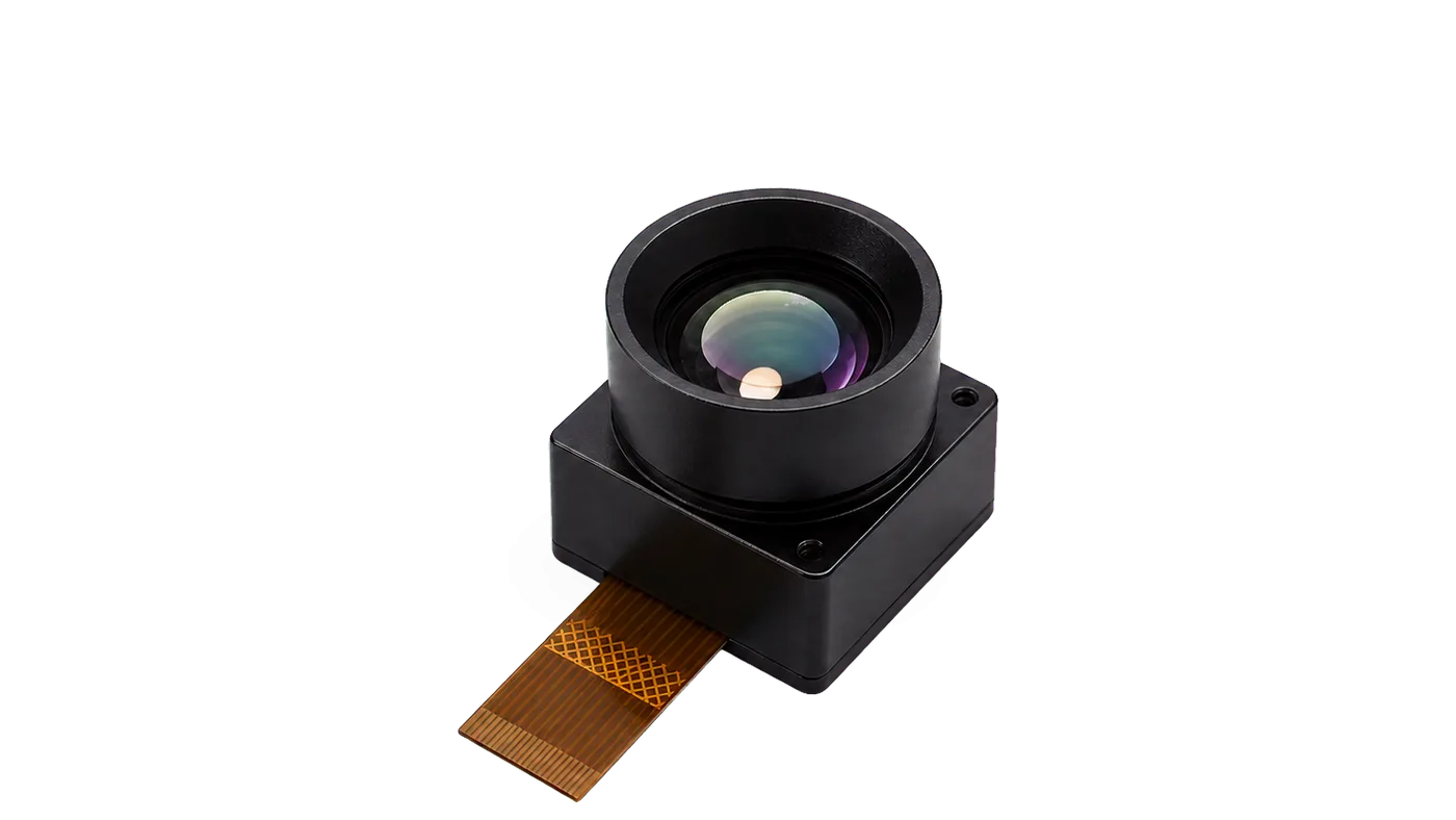
Every gram counts against battery chemistry. On a sub-7 kg quad or hexacopter, hanging an extra 50 grams of dead weight drops your total hover endurance by 3% to 7% based on your motor-prop efficiency curves. When integrating bare OEM cores—like the TC160-NF 160×120 LWIR Module—you get a sub-10 gram core that keeps overall payload mass low, cuts inertial resistance on direct-drive brushless gimbal motors, and extends flight times.
Power draw is just as critical. Cores that rely on active Peltier thermoelectric coolers (TEC) pull heavy current and dump heat inside sealed gimbal enclosures. Uncooled microbolometers bypass that power penalty entirely. High-efficiency bare cores run on minimal power (the TC160-NF draws ~76–78 mW reference at 3.3 V DC), barely registering on the aircraft’s power distribution board (PDB).
Keeping sensor power draw low is also vital for thermal stability. Heat from companion processors, step-down voltage regulators, or heavy sensor electronics can soak into the microbolometer substrate. That internal thermal gradient causes fixed-pattern noise (FPN), visual vignetting, and pixel drift. That forces the camera to run Non-Uniformity Correction (NUC) shutter cycles more frequently, freezing the live video stream right when your pilot or edge AI needs it most.
3. Payload Integration: Optics, Gimbals, and Interfaces
Building an industrial airborne thermal gimbal requires matching the right optical glass, mechanical vibration damping, and digital bus architecture.
Standard optical glass (BK7, fused silica) blocks 8–14 µm LWIR radiation completely. You must use specialized infrared materials, primarily optical-grade single-crystal Germanium (Ge) or molded Chalcogenide glass. Germanium gives you a high refractive index (~4.0 at 10 µm), enabling compact, low-profile lenses with minimal aberrations. But Germanium has a severe thermo-optic coefficient ($dn/dT$). Without an athermalized optical mechanical barrel, the lens loses focus as ambient temperatures shift from ground level to altitude (-20°C to +50°C). Lens elements also require multi-layer anti-reflective (AR) coatings inside and a rugged Diamond-Like Carbon (DLC) coating on the outer element to handle high-speed dust, grit, and moisture impacts during flight.
Your Field of View (FOV) and Instantaneous Field of View (IFOV) dictate how many millimeters of target surface each pixel covers from a given altitude Above Ground Level (AGL):
IFOV = Pixel Pitch (µm) / Focal Length (mm)
Ground Sample Distance (GSD) = IFOV · Flight Altitude (AGL)
Narrow-FOV telephoto lenses focus resolving power into small spots, delivering the tight GSD needed to spot cracked solar cells or failing transmission line splices from safe standoff distances. Wide-FOV lenses give wide situational awareness for obstacle avoidance, indoor flight, and wide search sweeps. For a detailed breakdown on selecting bare modules, check out our Infrared Camera Module OEM Buying Guide.
Airframe vibration is another major issue. Drone motors, high-frequency propeller blade passage (100 Hz to 1.5 kHz), and turbulent air currents shake the airframe. Since thermal microbolometers have fixed integration windows and thermal time constants, unmitigated vibration causes motion blur and rolling distortion. Practical vibration mitigation involves:
- ⚙️ Multi-Stage Passive Vibration Decoupling: Isolating the gimbal mounting plate with silicone or Sorbothane dampers (30A to 50A durometer) tuned to cancel out the main motor harmonics.
- ⚙️ Active 3-Axis Brushless Gimbal Stabilization: Running direct-drive brushless motors with 14-bit to 18-bit magnetic encoders (holding angular jitter under ±0.01°) driven by high-frequency field-oriented control (FOC) loops.
- ⚙️ Flexible Printed Circuit (FPC) Routing: Feeding signals through flexible 10-pin or 30-pin ribbon cables across gimbal axes to eliminate mechanical drag on the motors.
For your electrical interfaces, select a protocol that balances data throughput, EMI resistance, and host processing capacity:
- ⚙️ SPI (Serial Peripheral Interface): Ideal for lightweight, low-power micro-cores (like 160×120 arrays) talking directly to microcontrollers or companion boards over a compact 10-pin FPC connection.
- ⚙️ MIPI CSI-2: The industry standard for streaming uncompressed 14-bit or 16-bit raw radiometric frames directly into embedded Linux SoCs (NVIDIA Jetson, NXP i.MX8) at 25–60 FPS with near-zero CPU load.
- ⚙️ USB 2.0 / 3.0 (UVC Class): Great for fast prototyping on x86 and ARM SBCs, using native Linux Video4Linux2 (V4L2) drivers without writing custom low-level register code.
- ⚙️ CVBS (Analog Video): The legacy standard for zero-latency FPV piloting over 5.8 GHz analog transmitters, though it only carries AGC-compressed visuals with no per-pixel temperature telemetry.
4. Edge Compute, Telemetry, and Radiometric Processing Pipelines
Raw output from a microbolometer FPA arrives as uncalibrated 14-bit or 16-bit ADC values. Transforming those raw integers into calibrated temperature matrices and clear false-color video requires a multi-stage digital signal processing (DSP) pipeline.
The pipeline starts with Two-Point Calibration and Non-Uniformity Correction (NUC). Individual microbolometer pixels have slightly different gain slopes and offset intercepts. The processor applies per-pixel correction matrices to flatten the raw output. Next, Dead Pixel Replacement (BPR) flags dead or stuck pixels and interpolates their values from healthy neighbors. Then, Digital Detail Enhancement (DDE) and spatial filtering (like bilateral filters or CLAHE) separate broad background thermal shifts from fine structural edge details.
Downstream airborne data splits into two primary streams:
- ✅ Non-Radiometric AGC Stream: Dynamic Histogram Equalization crushes raw 14-bit data down to an 8-bit video feed (Ironbow, White Hot, Rainbow) optimized for pilot displays and low-bandwidth H.264/H.265 transmission to the Ground Control Station (GCS).
- ✅ Radiometric Telemetry Array: The full linear 14-bit/16-bit temperature array stays intact and feeds straight into onboard edge compute for automated threshold monitoring, isothermal boundary tagging, and hot-spot detection.
For autonomous operations, edge AI models (like YOLOv8-tiny or MobileNet-SSD) run right on the companion computer to spot human silhouettes, vehicles, or equipment hotspots during search-and-rescue or patrol missions. Developers can pull the raw stream using OpenCV for spatial filtering, contour checks, and radiometric matrix parsing. For networked autonomous drone fleets, thermal video feeds and telemetry metadata publish directly across ROS nodes using the standard image pipelines documented in the ROS 2 Documentation.
Bounding boxes and hot-spot coordinates pack directly into standard MAVLink messages (like CAMERA_IMAGE_CAPTURED or VISION_POSITION_ESTIMATE), letting the autopilot orbit a thermal target autonomously without manual pilot intervention.
5. Application Matrix: Selecting Resolution, Frame Rate & Lens Profiles
Matching camera specs to your operational environment prevents payload weight penalties or underspecified optical resolution. The matrix below maps key hardware requirements across common drone use cases:
| Application Domain | Flight AGL | Recommended Resolution | Pixel Pitch | Frame Rate | Critical Optical / Detection Metric |
|---|---|---|---|---|---|
| Close-Quarters Proximity & Indoor Navigation | 1 – 10 m | 160 x 120 | 35 µm reference | 25 FPS | Wide/Moderate FOV; minimal SWaP-C power draw (<80 mW) |
| HVAC & Building Envelope Auditing | 10 – 35 m | 256 x 192 / 384 x 288 | 12 µm – 17 µm | 25 – 30 FPS | High radiometric thermal sensitivity (NETD < 40 mK) |
| Utility-Scale Solar PV Inspection | 30 – 60 m | 640 x 512 | 12 µm | 25 – 30 FPS | Sub-module GSD (< 3.0 cm/px); high spatial resolving power |
| High-Voltage Grid & Substation Patrol | 20 – 50 m | 640 x 512 | 12 µm | 30 – 60 FPS | Narrow FOV telephoto optics; calibrated high-temp spans |
| Search & Rescue (SAR) & Wildfire Mapping | 50 – 120 m | 640 x 512 | 12 µm | 30 – 60 FPS | Dual-light optical/thermal fusion; human detection range > 500 m |
6. OEM Component & Observer Comparison Table
Engineering teams frequently pair onboard micro-sensor modules with handheld observation systems for ground verification. The table below compares embedded modules with rugged field systems from Camcuda:
| Parameter / Specification | TC160-NF Uncooled LWIR Module | Ura-Z Series Dual-Light Fusion Observer |
|---|---|---|
| Product Form Factor | Bare OEM Core / Embedded Module | Self-Contained Rugged Handheld Observer |
| Visual Reference |
|
|
| Thermal Array Resolution | 160 x 120 (19,200 total pixels) | 640 x 512 (327,680 total pixels) |
| Pixel Pitch | 35 µm reference | 12 µm |
| Spectral Range | 8 – 14 µm (LWIR) | 8 – 14 µm (LWIR) + Low-Light Visible Optical |
| Optical Configuration & FOV | Narrow-FOV fixed optics (56° D / 45° H / 34° V) | 35 mm manual focus lens (12.6° x 10.1° FOV) |
| Maximum Frame Rate | Up to 25 FPS | Real-time observation refresh rate |
| Operating Voltage / Power | 3.3 V DC (approx. 76–78 mW power draw) | Integrated battery architecture |
| Host Interface & Connector | SPI; 10-pin FPC (0.5 mm pitch reference) | Direct display eyepiece / integrated recording |
| Operating Temperature Range | -20°C to +85°C reference | -40°C to +50°C |
| Ingress Protection Rating | Module-level (enclosure-dependent) | IP66-rated rugged field housing |
| Weight & Dimensions | Sub-10 g (Ultra-compact footprint) | ≤ 1.0 kg; ≤ 153 x 150 x 68 mm |
7. Detailed Hardware Breakdown: Embedded Sensors vs. Field Observers
Embedded Core: TC160-NF 160×120 Uncooled LWIR Thermal Imaging Module
The TC160-NF 160×120 LWIR Module is an uncooled thermal core built specifically for embedded integration, micro-gimbals, and low-power IoT sensor packages. Built on a 160 x 120 focal plane array (19,200 active pixels) with a 35 µm pixel pitch reference, it covers the standard 8 µm to 14 µm LWIR spectrum.
The main engineering draw here is low power draw: it pulls just ~76–78 mW at 3.3 V DC. This minimal heat generation prevents thermal soak on tight companion carrier boards, removing the need for heavy copper heat spreaders or active cooling fans. The sensor streams factory-calibrated thermal data over a high-speed SPI bus via a 10-pin FPC ribbon interface (0.5 mm pitch reference), hooking straight into microcontrollers, flight companion boards, and edge processors. Its fixed narrow-FOV optics ($56^\circ \text{ D} / 45^\circ \text{ H} / 34^\circ \text{ V}$) provide concentrated target focus for close-range industrial monitoring, embedded perimeter security, and autonomous collision avoidance. Dedicated USB development boards are also available to speed up host driver and application testing.
| TC160-NF Technical Specifications | |
|---|---|
| SKU Reference | MI1602M5S |
| Resolution & Total Pixels | 160 x 120 (19,200 pixels) |
| Detector Pitch & Band | 35 µm reference; 8–14 µm (LWIR) |
| Frame Rate | Up to 25 FPS |
| Field of View (D/H/V) | 56° / 45° / 34° |
| Supply Voltage & Power | 3.3 V; ~76–78 mW reference power consumption |
| Host Bus & Connector | SPI; 10-pin FPC (0.5 mm pitch reference) |
| Operating Temperature | -20°C to +85°C reference |
| Calibration Status | Factory-calibrated thermal output |
View Product Details & Pricing ➔
Field Ground Observer: Ura-Z Series Dual-Light Fusion Handheld Thermal Observer
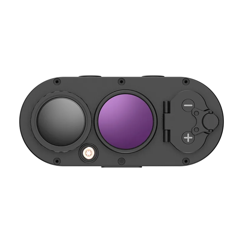
The Ura-Z Series Dual-Light Fusion Handheld Observer provides a rugged, high-resolution tool for ground teams validating aerial inspection findings. It combines a 640 x 512 uncooled thermal core (12 µm pixel pitch) with a low-light visible-spectrum optical channel.
Fitted with a 35 mm manual-focus lens, the Ura-Z provides a narrow $12.6^\circ \times 10.1^\circ$ field of view, delivering crisp detail on high-voltage splices, substation switches, or distant search targets. Its dual-light fusion engine overlays visible structural edges onto the thermal frame, making it easy to identify targets in complex environments or total darkness. Built for tough field duty, the unit features an IP66-rated housing, runs reliably from -40°C to +50°C, and weighs under 1.0 kg (dimensions ≤ 153 x 150 x 68 mm). It gives ground crews a dependable way to double-check aerial alerts immediately without hauling heavy diagnostic racks into the field.
| Ura-Z Series Technical Specifications | |
|---|---|
| Thermal Resolution | 640 x 512 |
| Pixel Pitch | 12 µm |
| Optical Lens | 35 mm manual focus lens |
| Field of View (FOV) | 12.6° x 10.1° |
| Operating Modes | Thermal, low-light visible, and dual-light fusion |
| Ingress Protection | IP66 rated |
| Operating Temperature | -40°C to +50°C |
| Dimensions & Mass | ≤ 153 x 150 x 68 mm; Weight ≤ 1.0 kg |
View Product Details & Pricing ➔
8. Step-by-Step OEM Integration & RFQ Checklist
When you’re sourcing bare thermal cores or designing custom aerial payloads, follow this engineering checklist to avoid common pitfalls. For a complete procurement framework, review our Thermal Camera Suppliers OEM RFQ Checklist.
- ⚙️ 1. Define Mission Profile & Flight Envelope: Pin down your exact use case (PV inspection, SAR, building envelope audit, obstacle avoidance) along with your typical flight altitude (AGL) and required standoff distance.
- ⚙️ 2. Ground Sample Distance (GSD) & Optics Selection: Calculate your target GSD (cm/pixel) to determine whether a 160×120 array meets your needs or if your mission requires a 640×512 array with telephoto optics.
- ⚙️ 3. Bus Topology & Electrical Interfacing: Choose the right hardware bus for your host platform—SPI for low-power MCUs, MIPI CSI-2 for embedded Linux companion computers, or USB UVC for fast bench prototyping.
- ⚙️ 4. Radiometric Requirements: Decide whether your software pipeline needs true per-pixel radiometric telemetry with active ambient drift compensation, or if an 8-bit AGC visual stream is sufficient.
- ⚙️ 5. Mechanical Layout & SWaP-C Budgeting: Set strict limits on module mass (sub-10 g for micro-cores), power draw (<80 mW), supply voltage stability (clean 3.3 V DC rail), and gimbal balancing limits.
- ⚙️ 6. Driver, SDK, & ROS Support: Ensure the core includes Linux V4L2 kernel drivers, C/C++ SDKs, Python bindings, and ROS 2 nodes for smooth host integration.
- ⚙️ 7. Supply Chain & Compliance: Confirm sample availability, production lead times, export classifications (ITAR/EAR), and NDAA compliance status early in the development cycle.
9. Frequently Asked Questions (Deep-Dive Engineering FAQ)
Why integrate an OEM thermal module instead of buying a proprietary thermal drone?
What video interface and protocol should be used for drone thermal payloads?
What thermal resolution is required for UAV inspection versus basic navigation?
📚 References & Further Reading
- Industry Standard: ROS 2 Documentation & OpenCV
- Related Guide: Infrared Camera Module OEM Buying Guide
- Related Guide: Thermal Camera Suppliers OEM RFQ Checklist
- Manufacturer Directory: Camcuda Thermal Imaging Solutions