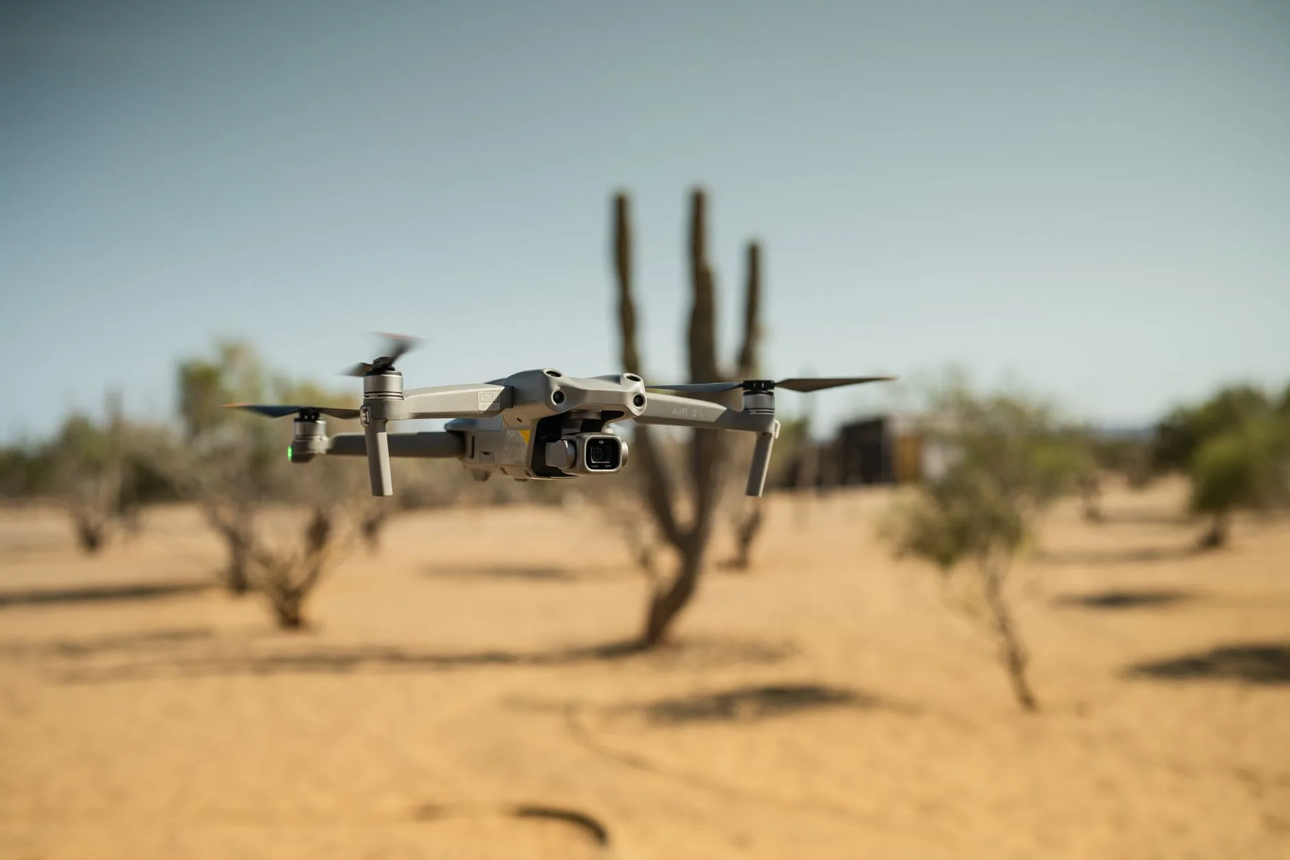
Thermal Imaging Drone Payloads: Sourcing LWIR Camera Modules for UAV Integration
Thermal Imaging Drone Payloads: Sourcing LWIR Camera Modules for UAV Integration
Look, building a rock-solid thermal imaging payload for unmanned aerial vehicles (UAVs) is never just about slapping a sensor onto a carbon-fiber plate. You are dealing with an uncompromising balancing act between infrared optical physics, detector sensitivity, rigid weight budgets, internal thermal dissipation, and communication latency. While off-the-shelf turnkey thermal drones offer a quick way to get airborne for basic jobs, they almost always box enterprise fleets and original equipment manufacturers (OEMs) into a corner with proprietary software stacks, locked gimbals, and sky-high repair bills.
Integrating uncooled Long-Wave Infrared (LWIR) OEM camera modules directly into your own custom airframes, 3-axis brushless gimbals, or autonomous edge-processing pods hands you full architectural control. This engineering approach slashes your bill-of-materials (BOM) costs while letting you dial in sensor resolution, optical fields of view, digital output pipelines, and telemetry synchronization to your exact operational flight envelope.
Whether you are designing micro-UAVs for tight indoor infrastructure audits, high-end tactical platforms for search-and-rescue (SAR) squads, or multi-rotors scanning utility-scale solar farms at 40 meters AGL, your choice of uncooled thermal core sets your platform’s operational ceiling and data fidelity. In this guide, we break down thermal detector physics, SWaP-C optimization, physical video interface protocols (SPI, USB, RS-422, and CVBS), infrared lens materials, and the real-world trade-offs between ultra-low-power micro-cores and high-resolution 640×512 radiometric payloads.
Table of Contents
- 👉 1. The Physics & Engineering of Drone-Mounted LWIR Systems
- 👉 2. SWaP-C Constraints in UAV Gimbal & Airframe Integration
- 👉 3. Video Transmission & Protocol Architecture: Analog CVBS vs. Digital USB/MIPI vs. SPI
- 👉 4. Core Comparison: Sourcing Uncooled LWIR Modules for Drone Payloads
- 👉 5. Critical Optical & Environmental Design Considerations
- 👉 6. Step-by-Step OEM Payload Integration & Prototyping Roadmap
- 👉 7. Commercial & Industrial Application Blueprints
- 👉 8. Comprehensive Drone Thermal Payload Engineering FAQ
1. The Physics & Engineering of Drone-Mounted LWIR Systems
Thermal imaging on an airborne rig works by harvesting electromagnetic radiation emitted within the Long-Wave Infrared (LWIR) band (8 to 14 μm). Standard visible-light electro-optical (EO) cameras depend entirely on reflected ambient sunlight or active illumination. An LWIR sensor, on the other hand, detects direct radiant energy emitted by every object in the scene above absolute zero, based on Planck’s radiation law, Stefan-Boltzmann equations, and surface emissivity dynamics outlined in Wikipedia – Thermography.
Up in the air, thermal contrast is driven by emissivity differentials, thermal inertia, and convective atmospheric cooling. To extract clean, actionable data from a moving airframe, your detector must resolve fractions of a degree across the scene while actively shrugging off aerodynamic noise, motor vibration, and sudden ambient temperature swings.
Microbolometer Architecture: Vanadium Oxide (VOx) vs. Amorphous Silicon (a-Si)
Modern UAV thermal payloads rely on uncooled microbolometer Focal Plane Arrays (FPAs). A microbolometer is essentially an array of microscopic pixel elements suspended over a silicon Readout Integrated Circuit (ROIC) by structural micro-bridges inside a vacuum-sealed package. When infrared photons strike the absorbing membrane, its temperature shifts, triggering a measurable change in electrical resistance that the ROIC digitizes into raw sensor counts.
Two primary semiconductor materials dominate microbolometer fabrication:
- ✅ Vanadium Oxide (VOx): The undisputed benchmark for industrial and tactical drone payloads. VOx delivers a high Temperature Coefficient of Resistance (TCR) alongside low 1/f electronic noise. In the shop, this translates directly to exceptional thermal sensitivity, higher Signal-to-Noise Ratios (SNR), and fast thermal response time constants. Fast pixel recovery prevents annoying image smearing and ghosting during rapid aircraft yaw, aggressive gimbal pans, or high-speed grid passes.
- ⚙️ Amorphous Silicon (a-Si): While a-Si detectors benefit from cheaper, standard silicon foundry manufacturing, they exhibit higher thermal time constants and elevated 1/f noise floors. That makes a-Si less ideal for dynamic aerial platforms where rapid airframe movements demand instantaneous frame-to-frame pixel recovery.
Noise Equivalent Temperature Difference (NETD)
Noise Equivalent Temperature Difference (NETD), rated in millikelvins (mK), is the true signal-to-noise benchmark of any thermal sensor. It represents the smallest temperature change the detector can resolve before hitting system noise. In flight, your NETD rating directly dictates whether you catch a fault or fly right past it:
- ✅ NETD ≤ 40 mK: High-end industrial sensitivity. Essential for aerial utility work where thermal anomalies are subtle—like early-stage cell degradation in solar arrays, hidden water pooling under flat roofs, or locating a human target beneath heavy forest canopy during a night SAR sweep.
- ⚙️ NETD ≥ 50 to 70 mK: Standard utility sensitivity. Fine for high-contrast tactical tracking, direct structural fire hot-spotting, or spotting gross industrial pipeline leaks, but prone to scene wash-out and dynamic range clipping when flying over low-contrast terrain at altitude.
Spatial Resolution, IFOV, and Ground Sampling Distance (GSD)
Selecting your sensor format and optical train comes down to calculating spatial sampling limits. The Instantaneous Field of View (IFOV) defines the exact angular footprint of an individual detector pixel in object space:
IFOV (mrad) = [Pixel Pitch (μm) / Lens Focal Length (mm)]
The resulting Ground Sampling Distance (GSD) dictates the physical surface patch covered by each pixel on the ground at a given flight altitude Above Ground Level (AGL):
GSD_thermal = Flight Altitude (m) × [Pixel Pitch (μm) / Lens Focal Length (mm)]
Moving from older 17 μm or 35 μm architectures down to a modern 12 μm pixel pitch lets you shrink your optical payload footprint dramatically while maintaining or even improving your spatial GSD at equivalent stand-off distances.
2. SWaP-C Constraints in UAV Gimbal & Airframe Integration
Integrating thermal camera modules into an aerial platform means living within strict SWaP-C (Size, Weight, Power, and Cost) boundaries. Every superfluous gram degrades battery endurance, shifts the center of gravity (CoG), and stresses your gimbal stabilization loop.
Weight and Mechanical Gimbal Balancing
In multi-rotor and fixed-wing gimbals, mechanical balance is everything. An uncooled thermal core weighing under 15 grams (like the HR21-L612-USB) drastically minimizes payload moment of inertia. This allows your mechanical team to utilize smaller, lower-torque brushless gimbal motors, reducing baseline power consumption and preventing high-frequency PID hunting or jitter during aggressive flight maneuvers or high-wind station keeping.
Power Dissipation and Thermal Management
Microbolometers detect minuscule temperature deltas across the FPA, so internal heat build-up inside the camera enclosure causes parasitic thermal drift and baseline signal degradation. Here’s the deal: a core drawing under 1.2 W at 25°C keeps internal electronic heating manageable. In fully sealed, IP67-rated airborne payload pods, design direct thermal conduction paths—like high-conductivity thermal gap pads mating the core chassis directly to a CNC-machined aluminum shell. This setup eliminates the need for heavy, power-hungry active cooling fans that add acoustic noise and parasitic drag.
Shock and Vibration Resilience
UAV airframes subject payloads to continuous high-frequency vibration from brushless motor harmonics (typically 100 Hz to 1.5 kHz) alongside sharp shock impulses on hard landings. Sourcing LWIR modules qualified to withstand 6.06 g random vibration across all axes and mechanical shock ratings exceeding 80 g @ 4 ms ensures structural integrity, preventing micro-fracturing on internal wire bonds, unseating of flexible printed circuits (FPCs), or optical defocusing under high-G dynamic loads.
3. Video Transmission & Protocol Architecture: Analog CVBS vs. Digital USB/MIPI vs. SPI
Your hardware interface determines video latency, CPU overhead on companion computers, and down-link bandwidth efficiency across your datalink.
Analog CVBS (Composite Video Baseband Signal)
For manual First-Person View (FPV) piloting, line-of-sight night navigation, and low-latency situational awareness, direct analog CVBS output remains an established industry standard. Routing analog baseband video straight into a 5.8 GHz analog video transmitter (VTX) delivers sub-10 millisecond glass-to-glass latency, bypassing the encoding and decoding delays inherent to digital streaming pipelines. For a detailed breakdown of analog transmission architectures, review our comprehensive engineering guide on CVBS thermal camera module analog video integration.
Digital USB & MIPI CSI-2
When integrating thermal payloads with onboard companion edge-AI computing platforms (such as NVIDIA Jetson Orin, Raspberry Pi CM4, or Qualcomm Flight architectures), digital data pipelines are essential:
- ✅ USB (UVC – USB Video Class): Standardized plug-and-play driver support across Linux and embedded ROS (Robot Operating System) environments. It pipes high-bandwidth digital video alongside real-time frame-by-frame 14-bit or 16-bit radiometric temperature metadata arrays.
- ⚙️ MIPI CSI-2: Bypasses host USB transceiver controllers entirely, routing raw pixel streams directly into the host processor’s Image Signal Processor (ISP) or hardware memory via Direct Memory Access (DMA). This setup provides an ultra-compact, lightweight connection path for edge-AI neural networks running real-time object detection and semantic segmentation.
SPI (Serial Peripheral Interface)
For ultra-compact IoT drones, micro-sensor payloads, or low-cost secondary obstacle-avoidance sensor arrays powered by low-power 32-bit microcontrollers (such as STM32, ESP32, or ARM Cortex-M cores), high-speed SPI provides a direct register access interface. It transmits raw, factory-calibrated frame data with minimal software overhead and exceptionally low electrical consumption (~75 mW).
Command and Control: RS-422 and USB Serial
Controlling the thermal module during flight—such as toggling pseudo-color palettes, commanding manual Non-Uniformity Correction (NUC) calibration cycles, adjusting digital zoom, or tuning Digital Detail Enhancement (DDE) parameters—demands robust serial communication. The use of balanced differential RS-422 communication guarantees high noise immunity against electromagnetic interference (EMI) generated by drone Electronic Speed Controllers (ESCs) and high-current power distribution boards, complying with aviation standards outlined by the ICAO Unmanned Aviation regulatory framework.
4. Core Comparison: Sourcing Uncooled LWIR Modules for Drone Payloads
Choosing between an ultra-low-power micro-core and a high-resolution aerial module depends on target flight altitude, spatial Ground Sampling Distance (GSD) requirements, and system power budgets. Explore our modular cores across the drone camera integration ecosystem.
TC160-NF 160×120 Uncooled LWIR Thermal Imaging Module
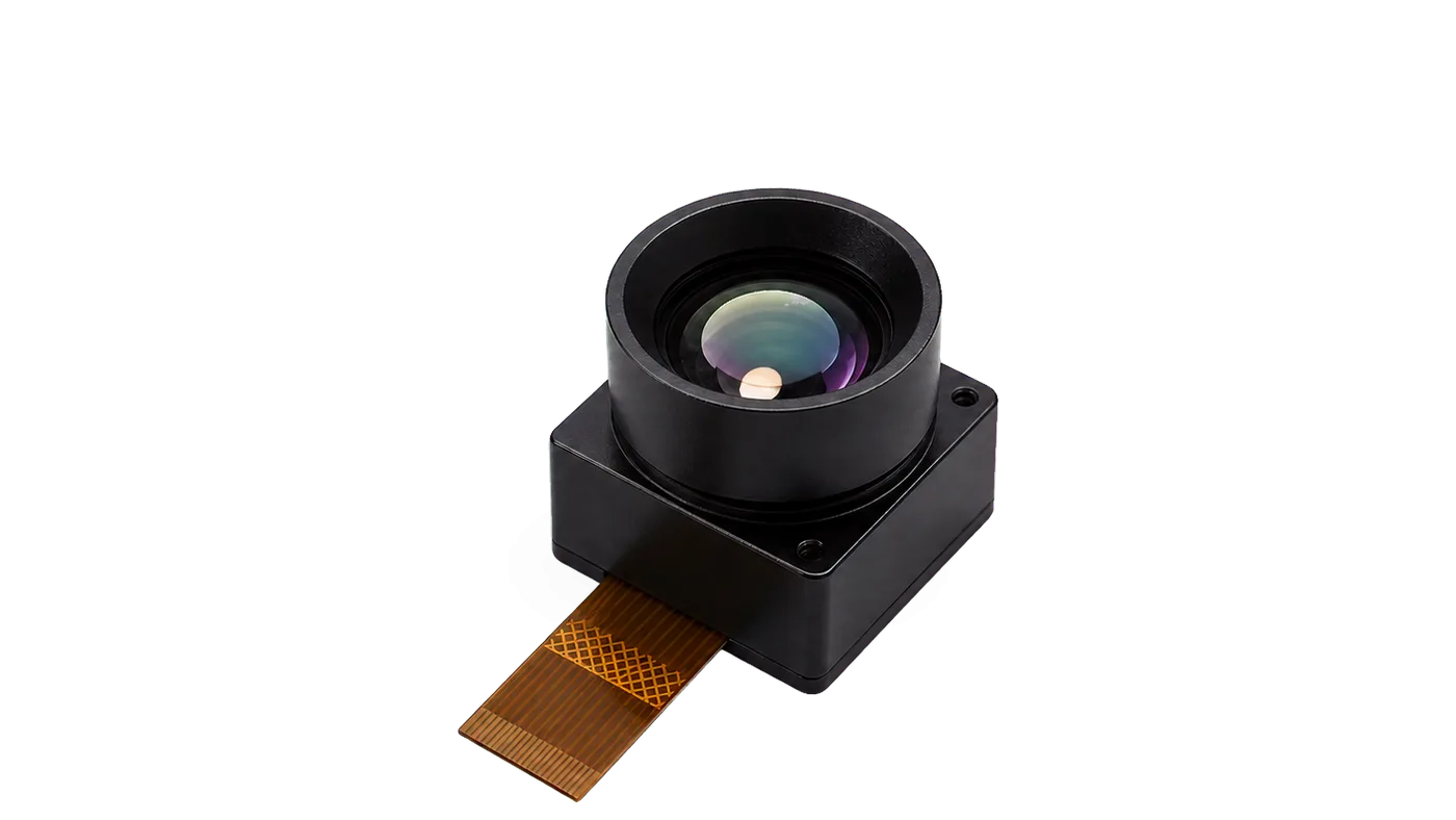
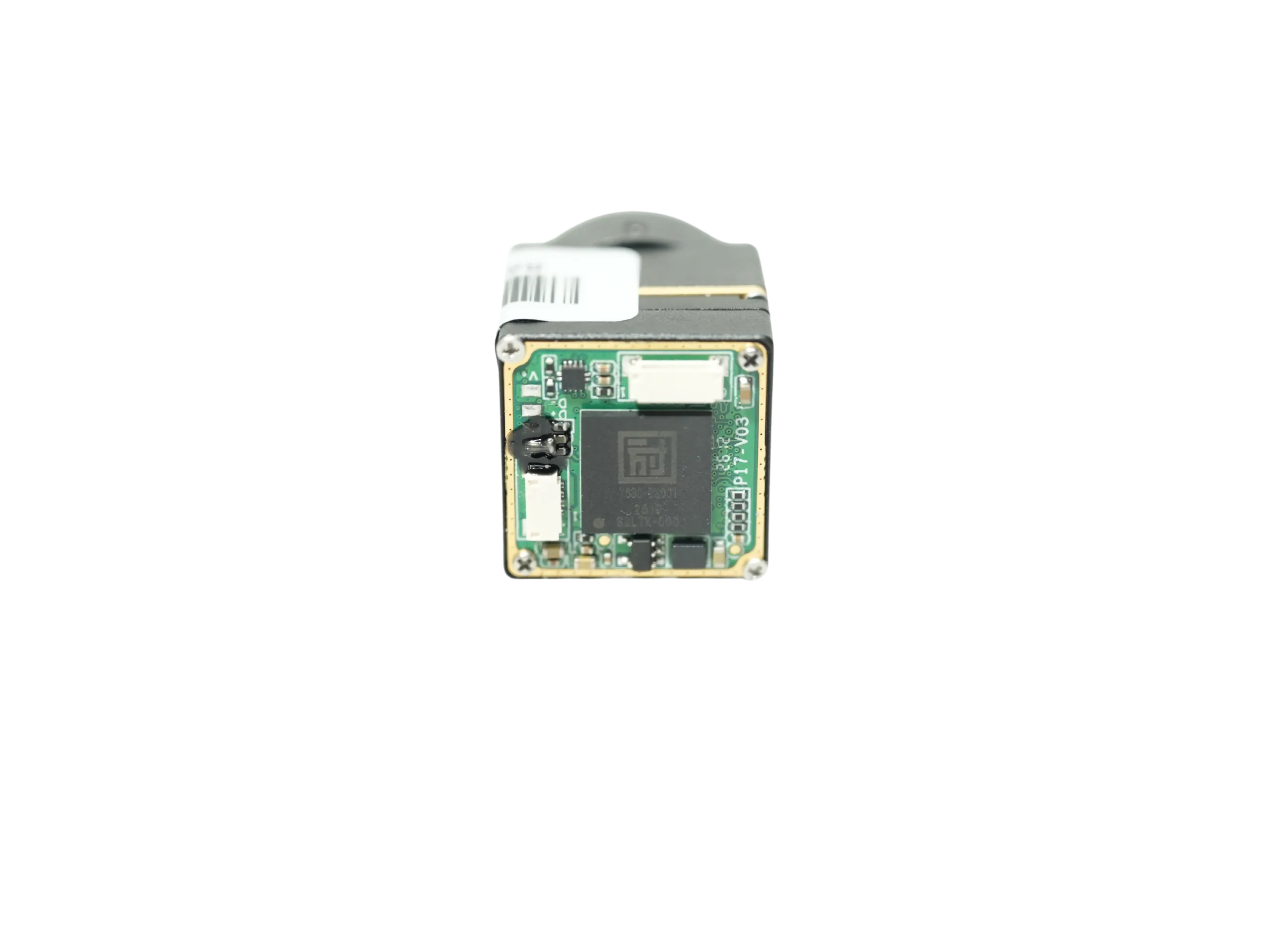
The TC160-NF is a compact uncooled LWIR thermal imaging module engineered for embedded thermal sensing, micro-UAVs, IoT edge devices, HVAC monitoring, and low-power OEM systems. Built around an SPI host interface, 3.3 V power rail, narrow-FOV optics, and factory-calibrated thermal output, it is tailored for embedded systems requiring a lightweight thermal sensor path before final enclosure design.
- ⚙️ Resolution & Array: 160 × 120 (19,200 total reference pixels), 35 μm detector pitch.
- ⚙️ Spectral Band & Speed: 8–14 μm LWIR band, up to 25 FPS frame rate.
- ✅ Power Footprint: Ultra-low power operation (~76–78 mW reference) on a single 3.3 V supply.
- ⚙️ Host Interface: High-speed SPI over a 10-pin FPC (0.5 mm pitch reference).
- ⚙️ Optical Geometry: Narrow-FOV fixed optical path (56° D / 45° H / 34° V).
- ✅ Operational Range: -20°C to +85°C reference operating temperature.
| TC160-NF Technical Specifications | |
|---|---|
| SKU Reference / Model | MI1602M5S / TC160-NF |
| Detector Class & Pitch | Uncooled LWIR FPA / 35 μm pitch reference |
| Field of View (FOV) | 56° / 45° / 34° (Diagonal / Horizontal / Vertical) |
| Supply Voltage & Power | 3.3 V Supply / Low-power 76–78 mW reference |
| Host Connector | 10-pin FPC, 0.5 mm pitch reference (USB eval board path available) |
| Calibration | Factory-calibrated thermal output |
HR21-L612-USB 640×512 Uncooled LWIR Thermal Imaging Module
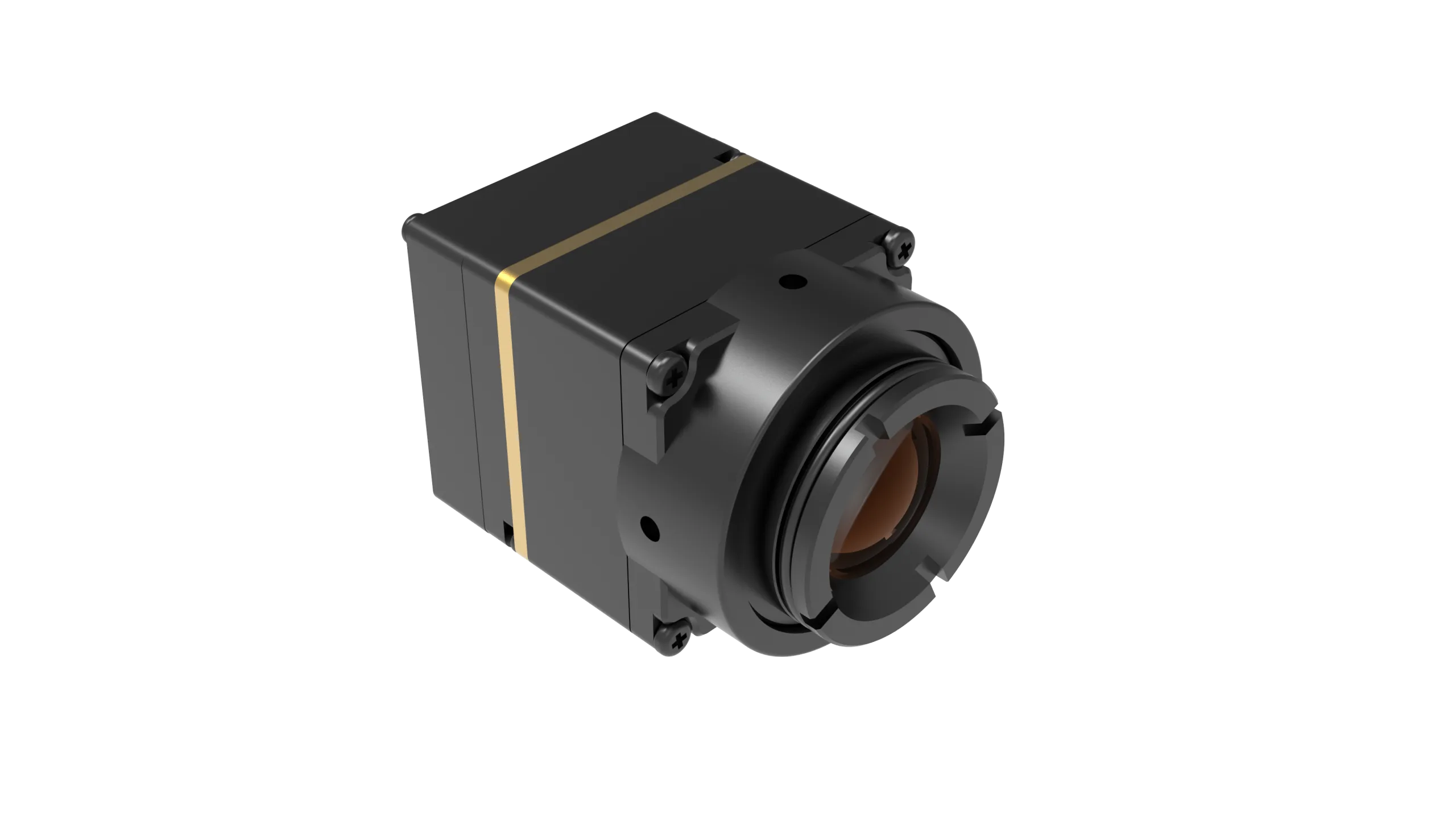
The HR21-L612-USB is a compact vanadium oxide (VOx) uncooled infrared UAV camera module engineered specifically for high-performance drone payloads, robotics, inspection platforms, and embedded vision systems requiring lightweight integration, USB digital video, and RS-422 industrial control.
- ✅ High Resolution Array: 640 × 512 resolution, 12 μm pixel pitch.
- ✅ Thermal Sensitivity: ≤40 mK NETD @ 25°C, F#1.0 for fine temperature gradient resolution.
- ⚙️ Frame Rate: Full 50 Hz detector frame rate for smooth aerial tracking.
- ✅ SWaP Optimized: Ultra-lightweight core weighing <15 g, compact 21 × 21 × 20.2 mm footprint.
- ⚙️ Versatile Video & Control: Digital USB video, USB serial communication, 1 × RS-422, with CVBS analog video support on applicable configurations.
- ⚙️ Advanced Image Engine: Onboard Non-Uniformity Correction (NUC), Digital Detail Enhancement (DDE), spatial/temporal filtering, and selectable pseudo-color palettes.
| HR21-L612-USB Technical Specifications | |
|---|---|
| Detector Type | Vanadium Oxide (VOx) Uncooled Infrared Focal Plane Detector |
| Resolution & Pixel Pitch | 640 × 512 / 12 μm |
| Frame Rate & Sensitivity | 50 Hz / NETD ≤40 mK @ 25°C, F#1.0 |
| Physical Dimensions & Weight | 21 mm × 21 mm × 20.2 mm / <15 g |
| Power Supply & Consumption | 5 V ±0.5 V / <1.2 W typical @ 25°C (including expansion board) |
| Video & Communication Paths | Digital USB, CVBS analog (select configs), USB Serial, 1 × RS-422 |
| Environmental Adaptability | -40°C to +85°C operating, 6.06 g random vibration, 80 g @ 4 ms shock |
Side-by-Side Payload Sourcing Matrix
| Parameter | TC160-NF Core | HR21-L612-USB Payload Core |
|---|---|---|
| Target Application | Embedded sensing, crawlspace micro-drones, HVAC audits | Professional UAV gimbals, SAR, industrial utility inspection |
| Detector Array | 160 × 120 pixels | 640 × 512 pixels |
| Pixel Pitch | 35 μm reference | 12 μm |
| Max Frame Rate | Up to 25 FPS | 50 Hz |
| Thermal Sensitivity | Factory Calibrated Industrial Grade | ≤40 mK @ 25°C, F#1.0 |
| Operating Power Draw | ~76–78 mW @ 3.3 V | <1.2 W @ 5 V |
| Core Module Weight | Micro scale (<5 g bare estimate) | <15 g |
| Primary Output Links | SPI Digital Stream | Digital USB + Analog CVBS + RS-422 |
5. Critical Optical & Environmental Design Considerations
Taking thermal cameras into the air exposes them to optical and physical conditions that bench testing never fully replicates. Flight speed, rotor downwash, rapid climbs, and sub-zero atmospheric temperatures require thoughtful optomechanical engineering.
Infrared Lens Materials and Protective Coatings
Standard optical glass (like fused silica or BK7) is completely opaque to infrared radiation in the 8 to 14 μm waveband. UAV thermal lenses demand dedicated materials:
- ⚙️ Monocrystalline Germanium (Ge): Germanium boasts a high refractive index (~4.0) and minimal optical dispersion across the LWIR spectrum, allowing for compact, fast (low F-number) optical designs. However, Germanium elements facing rotor downwash and atmospheric grit need Diamond-Like Carbon (DLC) hard anti-reflective external coatings. DLC coatings protect the outer glass from airborne particulate abrasion, driving rain erosion, and corrosive coastal salt fog.
- ⚙️ Chalcogenide Glass: Chalcogenide compounds can be precision-molded into intricate aspheric and diffractive profiles. This allows optical engineers to create lightweight, multi-element lens assemblies using fewer individual pieces, shaving critical grams off the gimbal assembly.
Athermalized Optical Assemblies
As your aircraft gains altitude, the temperature drops fast (standard atmospheric lapse rate sheds roughly 6.5°C every 1,000 meters). In basic fixed-barrel optics, thermal expansion and contraction shift the focal plane away from the microbolometer array, causing severe image defocusing. Airborne thermal payloads require passively athermalized lens assemblies. These utilize mechanically matched combinations of barrel materials (such as aluminum paired with Delrin or Invar sleeves) to maintain the exact optical back focal length across an operating envelope of -40°C to +85°C.
Non-Uniformity Correction (NUC) and Shutter Strategies
Every individual microbolometer pixel has slight gain and offset variances that shift as the camera’s internal temperature changes. Keeping imagery crisp and radiometrically uniform requires routine Non-Uniformity Correction (NUC):
- ⚙️ Mechanical Shutter NUC: A solenoid drops a uniform blackbody flag over the detector for 250 to 500 ms to refresh pixel offset tables. In autonomous flight, this brief video freeze must be managed carefully so autonomous visual tracking loops or obstacle-avoidance stacks do not lose state estimation mid-maneuver.
- ⚙️ Scene-Based Shutterless Correction: Advanced image processing algorithms track scene motion across multiple frames to estimate and subtract pixel offset drift continuously, eliminating the physical shutter entirely for uninterrupted target tracking.
6. Step-by-Step OEM Payload Integration & Prototyping Roadmap
Taking an uncooled LWIR core from benchtop prototyping to fully qualified airborne flight requires a disciplined, step-by-step systems engineering workflow.
-
⚙️ Phase 1: Lab Bench Bring-Up and SDK Evaluation
Start bench testing by interfacing the core with a host workstation using dedicated evaluation breakout boards. For USB cores (like the HR21-L612-USB), verify UVC driver enumeration, raw 14-bit data acquisition, palette switching, and RS-422 command telemetry. For SPI modules (like the TC160-NF), validate SPI clock polarity, timing margins, and frame synchronization lines against the host microcontroller. Review supplier procurement terms and our standard sample procurement and return policies when ordering engineering evaluation units. -
⚙️ Phase 2: Power Rail Conditioning and EMI Shielding
Microbolometer ROICs are extremely sensitive to voltage ripple. Drone power buses run dirty due to continuous high-frequency PWM switching noise from brushless ESCs. Never power your thermal core directly off an unregulated main battery bus or a noisy shared 5 V digital rail. Deploy a dedicated buck regulator followed by an ultra-low-noise Low-Dropout (LDO) linear regulator with high Power Supply Rejection Ratio (PSRR > 60 dB at 100 kHz). Wrap FPC ribbon cables in grounded copper or aluminum shielding tape and keep thermal signal runs physically isolated from high-power telemetry radios (like 915 MHz or 2.4 GHz transmitters). -
⚙️ Phase 3: Gimbal Mechanical Integration and Balancing
Lock the thermal core inside a rigid 6061-T6 aluminum housing or high-modulus carbon-fiber pod. Align the sensor core’s center of mass directly with the intersection of the gimbal’s roll, pitch, and yaw axes. Proper static mechanical balancing reduces steady-state holding torque on brushless gimbal motors, preventing motor overheating and extending flight battery life. -
⚙️ Phase 4: Telemetry Synchronization & Autopilot Integration
Map the camera’s control registers to standard autopilot message protocols (such as MAVLink payload control on PX4 or ArduPilot). Synchronize GPS position, barometric altitude, gimbal pitch/yaw angles, and LiDAR distance measurements with individual thermal frames, enabling downstream automated orthomosaic generation and radiometric photogrammetry workflows.
7. Commercial & Industrial Application Blueprints
Deploying thermal imaging drones across industrial environments addresses mission-critical challenges across multiple commercial verticals.
1. Utility-Scale Photovoltaic (PV) Solar Plant Auditing
Automated solar farm inspections require multi-rotors to survey thousands of photovoltaic panels at altitudes between 30 and 50 meters AGL. Utilizing a 640×512 resolution, 12 μm core with ≤40 mK NETD (such as the HR21-L612-USB) ensures that localized sub-cell hotspots, string degradation, cracked backsheets, and bypass diode failures are detected reliably during high-speed aerial passes without false positives caused by surface glint.
2. High-Voltage Transmission Line and Substation Monitoring
Corroded splices, failing transformer bushings, and phase imbalances generate localized thermal anomalies before catastrophic structural failure occurs. Flying a thermal drone along high-voltage corridors requires high sensitivity and a 50 Hz frame rate to eliminate image blur during parallel flight paths, while RS-422 differential signaling isolates camera control lines from high electromagnetic field interference around high-voltage lines.
3. Search and Rescue (SAR) & Wildfire Management
In search and rescue operations, locating lost persons under dense forest canopies or across rugged terrain requires maximum thermal contrast. A high-sensitivity uncooled core with adaptive Digital Detail Enhancement (DDE) reveals human heat signatures against cool ground clutter. In wildfire response, onboard thermal algorithms enable incident commanders to see through smoke and locate active fire perimeters, subterranean root fires, and spot flare-ups.
4. Confined-Space and Indoor Building Diagnostics
Navigating micro-UAVs inside industrial boiler tubes, building ducting, or attic crawlspaces requires ultra-lightweight, low-power sensor cores. Deploying a low-power, SPI-driven 160×120 core (like the TC160-NF) keeps total payload weight minimal and sensor power draw under 80 mW, preserving battery capacity on compact micro-drones designed for tight, enclosed spaces.
8. Comprehensive Drone Thermal Payload Engineering FAQ
Why are turnkey enterprise thermal drones so expensive, and how do OEM cores provide a cost-effective alternative?
What video interface and frame rate parameters are essential for UAV thermal integration?
When is a 160×120 resolution module sufficient versus requiring a 640×512 sensor core?
📚 References & Further Reading
- Industry Standard: ICAO Unmanned Aviation
- Scientific Principles: Wikipedia – Thermography
- Related Guide: CVBS Thermal Camera Module Analog Video Integration
- Product Ecosystem: Modular Drone Camera Integration Solutions
- Procurement Policy: CamCuda Evaluation & Refund Policy