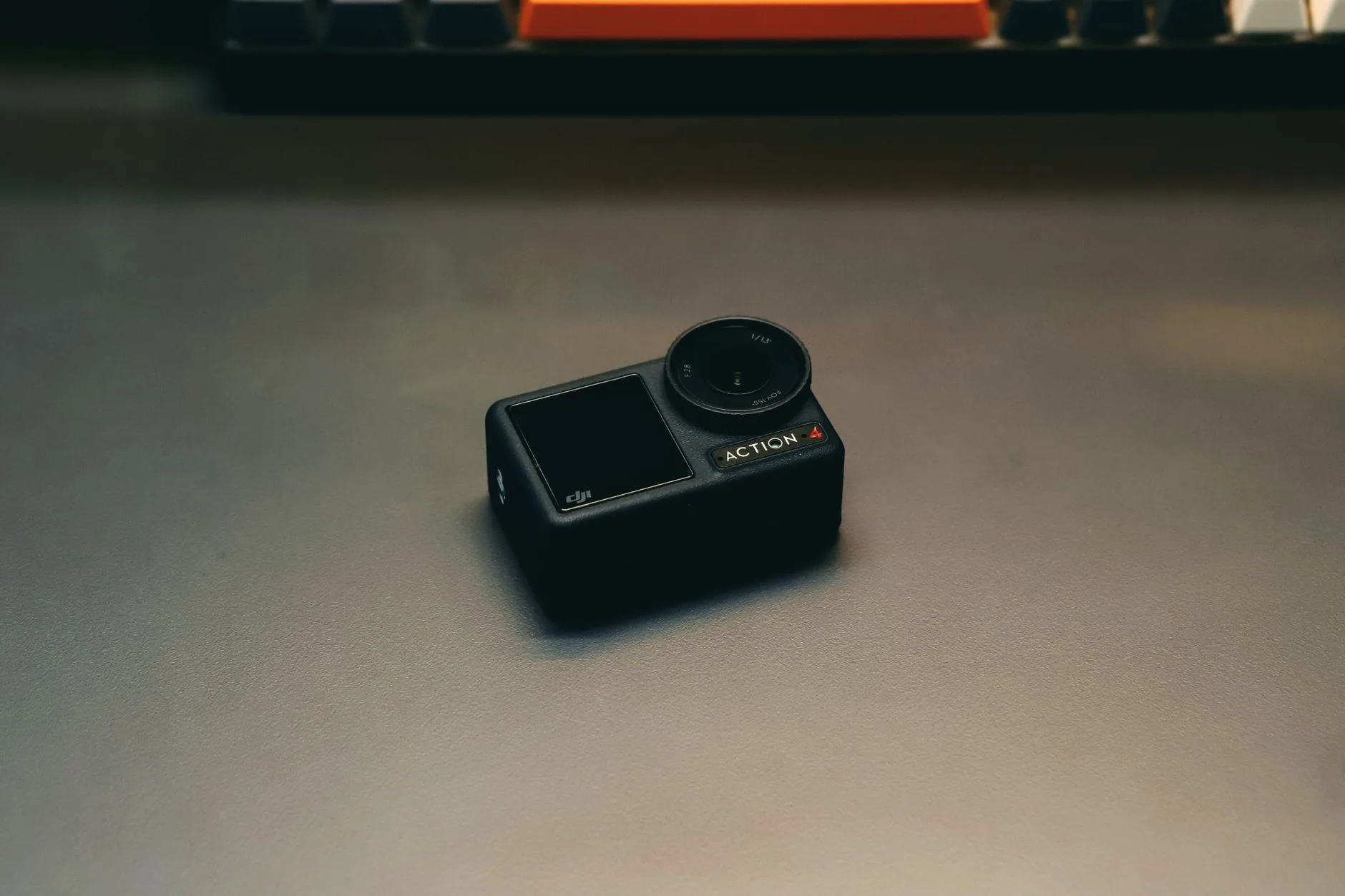
Cam Thermal Selection Guide: LWIR Cores vs Complete Cameras for OEM & UAV
Cam Thermal Selection Guide: LWIR Cores vs Complete Cameras for OEM & UAV
When you are designing embedded optical platforms, industrial automation rigs, or aerial inspection payloads, picking your cam thermal architecture is the single decision that makes or breaks the build. Here’s the deal: get it right, and your platform hits every Size, Weight, Power, and Cost (SWaP-C) target while delivering clean, low-latency thermal data. Get it wrong, and you will spend months chasing thermal throttling, jittery gimbal motors, frame drops, and painful integration bottlenecks. In the shop, we constantly see engineering teams wrestling with a fundamental choice: do you bolt on a heavy, off-the-shelf, fully enclosed thermal camera, or do you integrate a bare-board Long-Wave Infrared (LWIR) core directly onto your carrier board?
Packaged thermal cameras look tempting on paper because of their plug-and-play USB or Ethernet ports. But under the hood, they bring dead weight, redundant power regulators, sealed optics, and bloated protocol overhead that will crush your UAV flight times and bloat your mechanical envelope. Bare OEM LWIR cores strip away all the marketing fluff. They give your hardware direct access to raw digital transport buses—like native SPI, MIPI-CSI-2, parallel BT.1120, or broadcast-grade SDI. That means your host System-on-Chip (SoC) or FPGA can pull raw 14-bit radiometric frames straight into memory via Direct Memory Access (DMA) with zero unnecessary latency. This guide breaks down the core physics, optomechanics, electrical transport pipelines, and board-level thermal paths you need to master before cutting metal or printing circuit boards.
Table of Contents
- 👉 1. Understanding LWIR Detection Physics & Core Architecture
- 👉 2. Architectural Tradeoffs: Bare OEM Cores vs Enclosed Thermal Cameras
- 👉 3. Optomechanics: Germanium Windows, Lens Matching & FOV Geometry
- 👉 4. Electrical Interfaces & Video Transport Pipelines (SPI, MIPI, BT.1120, SDI)
- 👉 5. Comparative Analysis: Ultra-Low-Power vs High-Resolution LWIR Cores
- 👉 6. UAV & Drone Payload Design Considerations (SWaP, Gimbal, Compliance)
- 👉 7. OEM Sourcing & Host Board Integration Checklist
- 👉 8. Frequently Asked Questions (FAQ)
1. Understanding LWIR Detection Physics & Core Architecture
Thermal imaging does not work like standard visible-light machine vision. Visible sensors rely on reflected ambient photons bouncing off surfaces between 0.4 μm and 0.7 μm. Thermal imaging in the Long-Wave Infrared (LWIR) spectrum—specifically the 8 μm to 14 μm waveband—measures emissive blackbody radiation emitted directly by the physical targets themselves. According to Planck’s Radiation Law and Wien’s Displacement Law, objects at typical ambient earth temperatures (-40°C to +150°C) hit their peak electromagnetic radiation curves right inside this 8 to 14 μm sweet spot. Look at the atmospheric transmission spectrum: this specific band has minimal atmospheric attenuation from moisture and carbon dioxide, allowing an uncooled sensor to cut straight through total darkness, dense industrial smoke, fog, and light airborne dust.
At the center of any modern uncooled cam thermal module sits a microbolometer Focal Plane Array (FPA). In uncooled architectures, the sensing pixels are tiny thermistor membranes suspended over a silicon substrate by micro-machined bridge legs under a high vacuum seal. These membranes are typically fabricated from Vanadium Oxide (VOx) or Amorphous Silicon (α-Si). When incoming thermal radiation hits a pixel membrane, the absorbed energy changes its physical temperature, which instantly changes its electrical resistance. A high-density Read-Out Integrated Circuit (ROIC) bonded beneath the array samples these micro-resistance shifts by applying constant-bias voltages or integration currents across each row and column.
In high-performance industrial and aerospace systems, VOx has become the gold standard over older Amorphous Silicon builds. VOx yields a significantly higher Temperature Coefficient of Resistance (TCR) and much lower 1/f flicker noise. This translates directly to superior thermal sensitivity, rated in millikelvins (mK) as Noise Equivalent Temperature Difference (NETD). NETD represents the smallest temperature change the sensor can detect before the signal gets swallowed by underlying electronic thermal noise. A core with an NETD rating of ≤35 mK at f/1.0 pulls crisp thermal detail out of low-contrast scenes—such as finding subsurface moisture under composite roofs, cold air infiltration across building envelopes, or micro-ohm hot spots on dense power electronics—where a cheap ≤50 mK or 80 mK sensor produces a flat, noisy image.
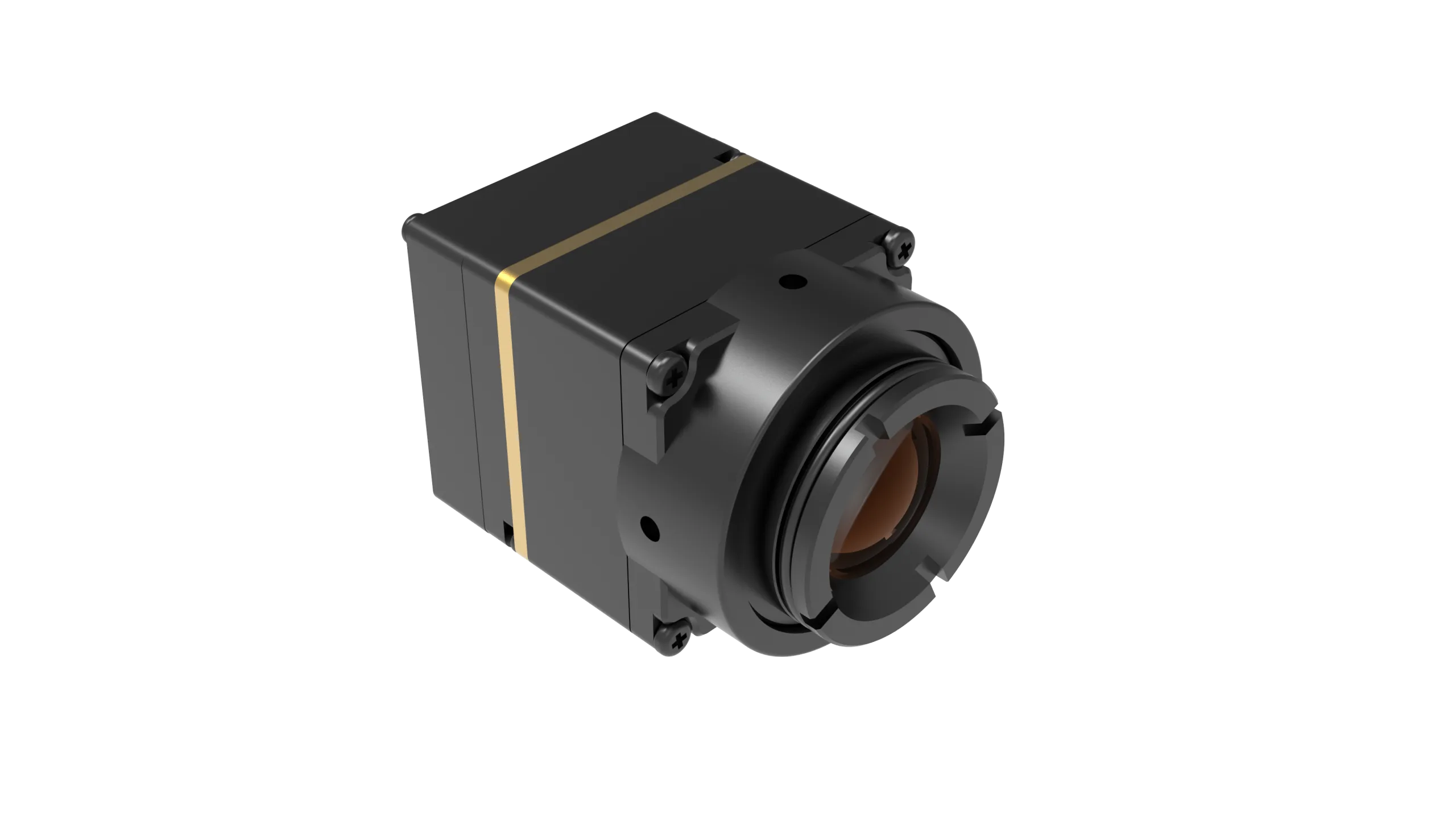
Pixel pitch is another critical parameter you cannot overlook. Over the last decade, pixel dimensions have shrunk from legacy 35 μm and 25 μm pitches down to modern 17 μm and 12 μm architectures. Why does this matter in the field? Shinking pixel pitch down to 12 μm reduces the physical footprint of the focal plane array for any target resolution. A smaller FPA requires a much shorter focal length to achieve the exact same optical Field of View (FOV). That directly shrinks your Germanium lens diameter, slashes barrel mass, and cuts the total optomechanical housing size in half. If you want to dive deeper into the raw physics of uncooled focal plane arrays, Optica hosts extensive peer-reviewed literature on infrared detector quantum efficiency and microbolometer fabrication.
Raw microbolometer arrays do not produce perfect, uniform images straight off the silicon. Every individual pixel has subtle manufacturing variances in baseline resistance and thermal response, creating a static background noise pattern known as Fixed Pattern Noise (FPN). To eliminate this, bare OEM cores use Non-Uniformity Correction (NUC) routines. Top-tier cores feature an internal, precision-timed electromechanical shutter that drops down periodically to give every pixel a flat thermal reference target. In flight environments where shutter freezes are unacceptable, advanced cores execute shutterless algorithmic NUC, analyzing continuous scene dynamics to balance pixel drift without mechanical interruptions.
2. Architectural Tradeoffs: Bare OEM Cores vs Enclosed Thermal Cameras
When you are laying out the architecture for an autonomous mobile robot, industrial process monitor, or aerial inspection pod, you have to decide where the boundaries of your camera subsystem lie. Picking between a finished, enclosed camera and a bare OEM module determines your mechanical design, power distribution, thermal cooling path, and software driver stack.
| Feature / Parameter | Bare OEM Core Module | Finished Industrial / Handheld Cam |
|---|---|---|
| Form Factor | Open-frame PCB stack, bare sensor array | Ruggedized, fully sealed housing (IP65/IP67) |
| Weight | Ultra-lightweight (<5g bare to 68g chassis) | Heavy (typically 250g to 1.5kg+) |
| Power Architecture | Direct 3.3V DC or wide 5–24V input | Regulated external 12V/PoE/Internal battery |
| Primary Interfaces | Raw SPI, MIPI-CSI-2, BT.656, BT.1120, SDI | USB-C, Ethernet (RTSP/ONVIF), HDMI, CVBS |
| Optical Flexibility | Interchangeable threaded mounts (M-mount/custom) | Fixed optical barrel with non-removable window |
| Transport Latency | Ultra-low (<1 frame cycle via DMA bus) | Protocol overhead (often 80–200ms latency) |
| Integration Effort | High (requires host PCB, driver, optomechanics) | Minimal (Plug-and-play desktop GUI / UVC driver) |
The core advantage of choosing a bare OEM module comes down to raw SWaP-C control. Finished industrial cameras wrap the core inside heavy aluminum enclosures, internal buck regulators, battery charging circuits, and bulky external connectors. On a workbench, that is fine. On an airborne UAV or a tactical handheld device, every extra gram costs precious seconds of battery run time. Bare modules allow you to strip out all redundant electronics and run the sensor directly off your system’s existing power distribution board.
Let’s talk latency and data integrity. Enclosed cameras typically convert the raw thermal sensor data into consumer-friendly formats like USB Video Class (UVC) or compress it into H.264/H.265 RTSP streams over Ethernet. That conversion pipeline adds anywhere from 80 ms to over 200 ms of latency. Worse, video compression algorithms throw away the raw 14-bit or 16-bit radiometric metadata, giving you nothing more than an 8-bit false-color rendering. With a bare OEM core, the raw temperature data streams straight over high-speed buses into your processor’s memory buffer via DMA. Your computer vision algorithms can analyze real physical temperatures pixel by pixel with near-zero latency.
To see how to verify board-level hardware interfaces and debug timing issues during prototype bring-up, check out our in-depth walkthrough on IR camera module drone and OEM integration checks.
3. Optomechanics: Germanium Windows, Lens Matching & FOV Geometry
Here is one of the most expensive mistakes rookie engineers make in the shop: designing a custom weatherproof enclosure and putting a piece of standard optical glass, sapphire, or polycarbonate over the thermal camera lens. Standard silicate glasses (like BK7, fused silica, and float glass) and clear plastics are 100% opaque to LWIR photons between 8 μm and 14 μm. If you mount an uncooled core behind a standard glass window, your thermal camera will be completely blind, imaging nothing but its own internal thermal reflection.
If you need a protective viewport or custom lens stack, you have to use specialized infrared optical substrates:
- ✅ Monocrystalline Germanium (Ge): The undisputed heavyweight of LWIR optics. Germanium provides exceptional mechanical hardness and a high refractive index (~4.0), which lets optical engineers design compact, high-power lens profiles. Because bare Germanium reflects roughly 36% of light per surface due to Fresnel reflection, it must be treated with high-durability Anti-Reflective (AR) or Diamond-Like Carbon (DLC) coatings to hit transmission levels above 95%.
- ✅ Chalcogenide Glass (such as GASIR or IG6): A specialized family of amorphous glasses containing Germanium, Selenium, and Antimony. Chalcogenide optics have an exceptionally low thermal focal drift (low dn/dT). This keeps your thermal image pin-sharp across wide temperature swings (-40°C to +85°C) without needing complex electromechanical refocusing mechanisms.
- ✅ Zinc Selenide (ZnSe): Provides broad multi-spectral transmission across both the visible and LWIR spectra. ZnSe is the go-to material when your system needs to project a visible targeting laser and an LWIR thermal channel through the exact same optical window.
Matching your lens focal length to your target operational distance dictates both your field of view and your spatial resolution. Horizontal Field of View (HFOV) is governed by basic trigonometric optical math:
HFOV = 2 × arctan [ Sensor Width / (2 × Focal Length) ]
To find Sensor Width, multiply your horizontal pixel count by your pixel pitch. Take a high-resolution 1280×1024 sensor with a 12 μm pixel pitch: its active horizontal detector width is 15.36 mm (1280 × 0.012 mm). If you screw on a 25 mm lens, you get an HFOV of roughly 34.1 degrees. Swap that out for a 100 mm telephoto lens, and your HFOV narrows down to 8.8 degrees, concentrating your pixel density onto distant targets.
As a rule of thumb, wide-FOV optics (45° to 90°) are ideal for short-range applications like industrial electrical cabinet scanning, HVAC duct profiling, and robotic obstacle avoidance. Narrow-FOV optics (<20°) are mandatory for airborne power line inspections, high-altitude drone surveillance, and perimeter security where you need high pixel counts on targets hundreds of meters away.
4. Electrical Interfaces & Video Transport Pipelines
Choosing your electrical transport interface is where your hardware architecture meets your software stack. You have to balance raw pixel bandwidth, physical track lengths, pin counts, and host processing capability.
| Interface Protocol | Data Bandwidth | Bus Characteristics | Target Host Processor |
|---|---|---|---|
| SPI (Serial Peripheral Interface) | 10 – 50 Mbps | 4-wire synchronous, single-ended | Low-power MCUs (STM32, ESP32, Cortex-M) |
| MIPI-CSI-2 | Up to 1.5 Gbps/lane | Low-voltage differential signaling (LVDS) | Embedded SoCs (NVIDIA Jetson, NXP i.MX8) |
| BT.656 / BT.1120 | Parallel clock/data | 8/16-bit parallel CMOS logic | FPGAs (Xilinx, Altera), DSP video processors |
| HD-SDI / 3G-SDI | 1.485 – 2.97 Gbps | 75 Ω coaxial, long-distance serial | Drone video transmitters, broadcast encoders |
| CameraLink | Up to 2+ Gbps | Multi-channel LVDS dedicated industrial | Industrial frame grabbers, machine vision IPCs |
For compact, battery-powered sensor nodes, Serial Peripheral Interface (SPI) is an outstanding choice. On low-resolution modules (such as 160×120), pushing 14-bit raw pixel data generates a clean data rate that an ARM Cortex-M microcontroller can ingest directly over high-speed SPI using DMA burst transfers. You do not need external DDR RAM or a heavy embedded Linux OS to process temperature readings. That keeps your bill-of-materials cost minimal and your power draw measured in milliwatts.
Once you step up to high-definition thermal imaging (such as 1280×1024 at 50 Hz), the data rate explodes. Shuffling 1.3 million pixels at 16-bit depth 50 times a second pushes throughput beyond 1.0 Gbps. A simple SPI bus will choke instantly. To handle this firehose, you need dedicated parallel buses like BT.1120 or high-speed serialized links like HD-SDI or CameraLink. These interfaces pipe directly into hardware FPGAs or embedded GPU SoCs, allowing real-time spatial filtering, palette rendering, and neural network inference without dropping a single frame.
5. Comparative Analysis: Ultra-Low-Power vs High-Resolution LWIR Cores
Let’s look at how these engineering principles translate into physical hardware. Below is a head-to-head comparison between an ultra-low-power embedded sensing core and a high-definition, high-framerate LWIR engine.
TC160-NF: 160×120 Uncooled LWIR Thermal Imaging Module
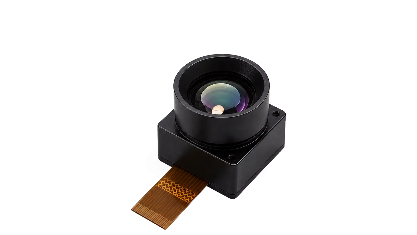
The TC160-NF is a featherweight, uncooled LWIR core purpose-built for embedded IoT sensing, smart building hardware, HVAC monitoring, and battery-constrained OEM designs. Built around a 160×120 uncooled focal plane array with a 35 μm pixel pitch, this module delivers factory-calibrated radiometric thermal data across the 8–14 μm spectral band at up to 25 FPS.
In the shop, the headline feature of the TC160-NF is its ultra-lean power profile: it runs on a single 3.3V DC rail and draws only 76 to 78 mW during standard operation. It connects to your host MCU via a high-speed SPI bus over an ultra-compact 10-pin Flexible Printed Circuit (FPC) connector (0.5 mm pitch). Its integrated optical barrel delivers a fixed field of view of 56° Diagonal, 45° Horizontal, and 34° Vertical, making it a drop-in solution for close-quarters thermal anomaly detection.
| Detector & Optical Specifications | |
|---|---|
| Model / SKU Reference | TC160-NF / MI1602M5S |
| Array Resolution & Pixels | 160 × 120 (19,200 total pixels) |
| Pixel Pitch & Spectral Band | 35 μm reference | 8 – 14 μm LWIR |
| Frame Rate & FOV | Up to 25 FPS | 56° D / 45° H / 34° V |
| Electrical, Interface & Environmental | |
| Supply Voltage & Power | 3.3 V DC | ~76 – 78 mW ultra-low power |
| Host Bus & Physical Connector | SPI | 10-pin FPC (0.5 mm pitch reference) |
| Operating Temperature | -20°C to +85°C reference |
| Calibration & Eval Support | Factory calibrated; USB evaluation board path available |
HR-1280: 1280×1024 Uncooled VOx Thermal Imaging Module
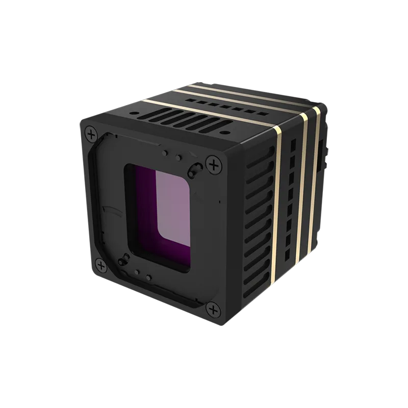
The HR-1280 is a heavy-duty, high-definition uncooled VOx LWIR imaging engine engineered for high-altitude UAV gimbals, long-range security systems, and high-speed industrial vision. Packing a native 1280×1024 resolution with a tight 12 μm pixel pitch, this module delivers over 1.3 million active thermal data points at a fluid 50 Hz frame rate.
With an NETD sensitivity rating of ≤35 mK (@ 25°C, f/1.0), the HR-1280 reveals tiny thermal gradients through harsh atmospheric interference. For video transport, it supports BT.656, BT.1120, SDI, and CameraLink digital interfaces, alongside RS232, RS485, and RS422 serial links for remote camera control. Weighing only 68 g (without lens) in a 35 × 35 × 35 mm aluminum housing and handling a wide 5–24V input rail, it drops cleanly into drone gimbals. It also supports an extensive lineup of interchangeable Germanium lenses (9 mm through 100 mm), giving you complete control over your focal geometry.
| Detector & Thermal Performance | |
|---|---|
| Detector Type & Resolution | Uncooled VOx | 1280 × 1024 pixels |
| Pixel Pitch & Spectral Range | 12 μm | 8 – 14 μm response band |
| Frame Rate & Sensitivity | 50 Hz | NETD ≤ 35 mK @ 25°C, F#1.0 |
| Lens Options Available | 9 / 13 / 19 / 25 / 35 / 50 / 75 / 100 mm options |
| Electrical, Video & Mechanical | |
| Input Voltage Range | 5 – 24 V DC wide-range input |
| Digital Video Output | BT656 / BT1120 / SDI / CameraLink (CVBS not supported) |
| Control Communication | RS232 / RS485 / RS422 serial protocols |
| Dimensions & Weight | 35 × 35 × 35 mm | 68 g without lens |
| Compliance | NDAA statement available upon request |
6. UAV & Drone Payload Design Considerations (SWaP, Gimbal, Compliance)
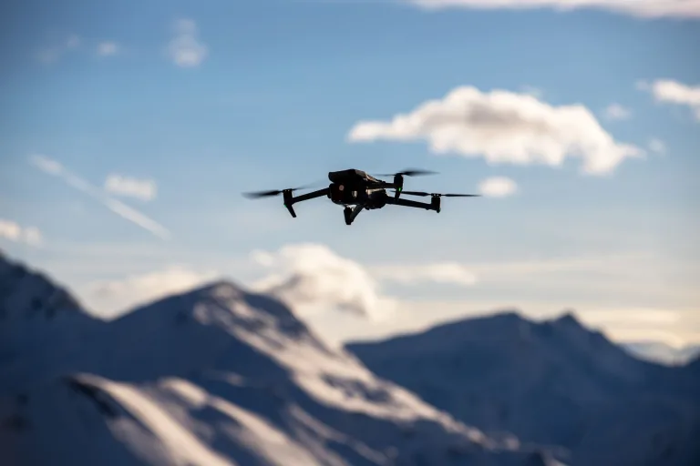
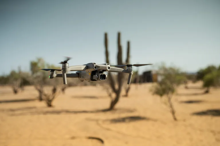
Mounting an uncooled cam thermal module onto an airborne drone platform is a whole different ballgame compared to bolting it onto a factory floor. In flight, your payload faces continuous mechanical vibration, severe aerodynamic drag, wide thermal gradients, and intense electromagnetic interference from nearby brushless motors.
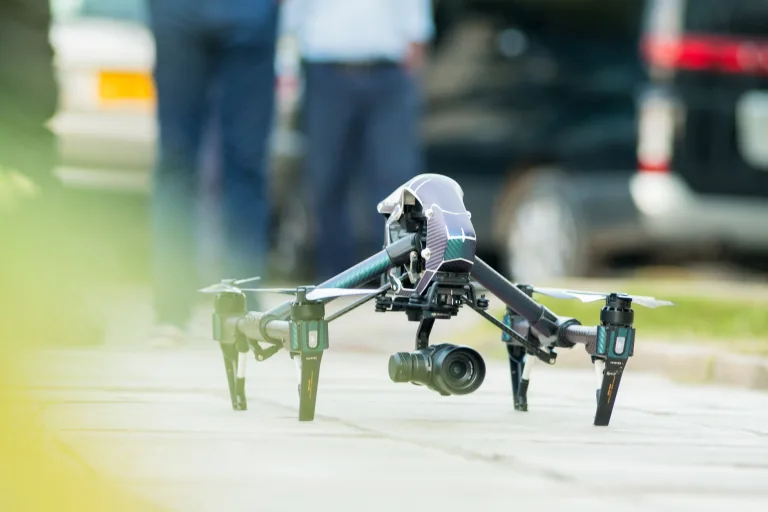
When tuning a 3-axis brushless gimbal, your mechanical Center of Gravity (CoG) is everything. If your camera mass is offset from the pitch and roll rotational axes, your gimbal motors must pull continuous high current just to keep the camera level. This extra load overheats the motor windings, creates high-frequency micro-jitter in your video feed, and drains your main flight battery. A bulky consumer camera makes balancing nearly impossible due to its asymmetrical shape. An OEM core like the HR-1280 (weighing just 68 g in a symmetrical 35 mm cube) allows you to align the mass directly at the rotational intersection, slashing motor torque requirements and maximizing flight endurance.
Electrical noise is another major hazard on UAVs. High-current Electronic Speed Controllers (ESCs) and brushless motors dump severe high-frequency switching noise back onto the shared DC power bus. Because microbolometer ROICs measure tiny micro-volt resistance changes across each pixel, voltage ripple on the camera power rail turns directly into horizontal banding noise and tanked NETD sensitivity. In the shop, we require a dedicated LC low-pass filter or low-noise LDO regulator on the thermal camera supply line, paired with grounded copper foil shielding around all flexible flat cables to block 5.8 GHz video transmitter emissions.
On the regulatory side, if you are flying commercial thermal inspection, search-and-rescue, or perimeter patrol missions in the United States, your entire aircraft and payload setup must follow the Federal Aviation Administration’s guidelines under eCFR Part 107 Small Unmanned Aircraft Systems. Keep your total payload weight within certified maximum takeoff limits (MTOW), ensure proper visual observer protocols for night flights, and verify that your hardware complies with all operational safety standards.
7. OEM Sourcing & Host Board Integration Checklist
Before you commit to volume procurement or send your carrier PCB gerbers off to fabrication, run through this board-level engineering integration checklist:
- ⚙️ 1. Optomechanical Viewport Material: Confirm that your outer protective window is made from AR/DLC-coated Monocrystalline Germanium, Chalcogenide glass, or Zinc Selenide. Double-check that no standard silicate glass or acrylic plastic is in the LWIR optical path.
- ⚙️ 2. Power Distribution & Rail Cleanliness: Verify that your power rail delivers clean DC voltage (e.g., dedicated 3.3V LDO for the TC160-NF, clean 5–24V rail for the HR-1280). Make sure your power supply handles the initial peak in-rush current during microbolometer bias power-up without voltage sags.
- ⚙️ 3. Bus Clock & DMA Ring Buffers: For SPI designs, confirm that your SPI clock frequency, clock polarity (CPOL), and clock phase (CPHA) match the module’s datasheet. Allocate sufficient DMA ring-buffer memory on your host MCU to prevent dropped packets during heavy interrupts.
- ⚙️ 4. Cable Strain Relief & Vibration Hardening: Inspect the FPC connector locking mechanism (e.g., 10-pin 0.5 mm pitch) and design mechanical strain relief tabs into your chassis to keep cables secure under high drone vibration profiles.
- ⚙️ 5. Thermal Heatsinking & Heat Sinks: Build a direct conductive thermal path (using thermal gap pads to an aluminum frame) from the core’s rear housing. Trapping heat inside the camera enclosure will distort the internal microbolometer temperature calibrations.
- ⚙️ 6. Video Pipeline Bus Matching: Make sure your host SoC or FPGA video input port natively supports the required bus protocol (BT.1120, SDI, CameraLink) and control lines (RS232, RS485, RS422). Keep in mind that legacy CVBS analog output is not supported on high-definition modules like the HR-1280.
- ⚙️ 7. Export & Procurement Policies: Verify NDAA statements and procurement agreements before signing off on purchase orders. Review commercial terms and return policies detailed under our Terms of Service and Refund Policy.

8. Frequently Asked Questions (FAQ)
Can I integrate a consumer-grade USB thermal camera dongle directly into an OEM drone payload or embedded appliance?
Why is optical Germanium mandatory for thermal camera viewports instead of standard tempered glass?
How do I determine the appropriate resolution: 160×120 vs 1280×1024 for my project?
📚 References & Further Reading
- Industry Standard: Optica (Optical Society of America) Technical Publishing
- Regulatory Standard: eCFR Part 107 Small Unmanned Aircraft Systems
- Related Guide: IR Camera Module Drone and OEM Integration Checks